Abstract
Adhesive bonding is widely used in many industries,including civil engineering. Since adhesives usually have a lower strength than the materials they join,selecting the right adhesive is essential for ensuring durable joints. One of the main challenges is the concentration of stresses at the free edges,which can lead to premature failure. To address this issue,researchers have suggested modifying the overlap geometry by adding tapers or fillets to improve load distribution and minimize stress concentrations. This study evaluates the mechanical performance of a bonded joint between two aluminum alloy plates using Adekit A140 adhesive through finite element analysis. We investigate geometric modifications to the free edges of the plates and the adhesive to mitigate stress concentrations. The analysis considers parameters such as overlap length,applied load and the specific edge geometries of the adhesive and substrates. The results clearly demonstrate that the joint's mechanical strength is strongly influenced by these geometric alterations,which depend closely on the overlap length,underlining their importance in enhancing joint performance. The choice of optimal geometric parameters for modifying the adhesive and plate edges significantly reduces stress concentrations and ensures good mechanical resistance for large overlap lengths. However,for shorter overlaps,these modifications may reduce the joint's strength.
0 Introduction
In modern structures,adhesive joints play a crucial role in assembly techniques,particularly in various sectors such as aeronautics,automotive. They constitute an excellent alternative to traditional methods such as welding or riveting,due to their lightness,uniform distribution of stresses,no damage to the assembled substrates,and the ability to combine materials of different natures while maintaining their long-term resistance[1-3]. On the other hand,the strength of these single-lap joints(SLJ)can be affected by the presence of high stresses,such as von Mises and peel stresses,which can negatively impact their durability and mechanical performance.
Over the years,many studies have been carried out to optimize adhesive joints. Goland and Reissner[4] were the first to present the first modern theory of lap joints. Subsequently,Hart-Smith[5] was one of the first to improve the basic theories of Goland and Reissner,in particular by describing the way in which stresses are distributed in the joints. Research has shown that it is possible to improve the strength of an SLJ by modifying its mechanical and geometrical properties[6-12]. In this context,some authors have studied the adhesive thickness effect and adhesion geometry in enhancing the strength of an SLJ[13-18]. In an experimental study,Mariam et al.[19]demonstrated that hybrid joints with different bond strengths offer the optimum combination of strength and stiffness. A numerical model of a single-lap assembly has been developed and calibrated based on experimental results and published numerical predictions[20-22]. Recently,researchers have focused on innovative geometric solutions. Barbosa et al.[23]studied the performance of bonded joints according to their geometry(single-lap joint(SLJ),double-lap joint(DLJ),stepped-lap joint and scarf joint)and the type of adhesive used.Their results show that the optimal configuration depends on the properties of the adhesive:scarf joints are more suitable for fragile adhesives with uniform stress distribution,while double-lap joints are optimal for ductile adhesives due to their larger bonded area.Ayatollahi et al.[24]investigated the effect of the interfaces on the performance of single-lap bonded joints. They found a 49% increase in static strength and a significant improvement in fatigue life compared to planar interfaces. These non-planar interfaces enhanced mechanical performance and improved the durability of bonded joints by extending the crack initiation phase. Ramaswamy et al.[25]demonstrated that an asymmetric spew geometry reduced the undesirable effects of the eccentricity angle and improved the stress distribution in the adhesive. The flat sprue configuration showed an energy absorption capacity between 90% and 120% greater than the half-round spew joints under dynamic loads.Bahrami et al.[26]suggested improving the mechanical performance of adhesive joints by adding a notch to the materials to be joined after the overlap length.They found that a notch with a depth of 20% could increase the strength of the joint by up to 60%. Similar work by Khosravani et al.[27]showed that the failure load of the joints increased by 49. 31% due to a reduction in stress concentrations in the adhesive caused by the addition of notches. In another study by Bayramoglu and Akpinar[28],the effect of recesses and notches in the bonding material on the strength of the assembly was examined. They found that the introduction of recesses in the outer part of the overlap area increased the strength of the joint by approximately 29%,while notches improved the strength by 27%. Recently,several studies have explored geometric strategies for improving the mechanical performance of bonded joints. For example,Çalık[29]used finite element modeling to study the effect of reinforcement patches added to single-lap joints. Their parametric analysis revealed that the thickness,length and position of these patches significantly influenced the distribution of shear and peel stresses in the bond zone,leading to a reduction in stress concentrations and an increase in the global strength of the joint.
However,while many different approaches have been proposed in the literature to improve the mechanical performance of SLJ,the majority of works have focused on either adhesive properties or joint geometry,but rarely on the combination of these aspects. In particular,the combined effect of geometric modifications to substrate edges and adhesive shape on stress distribution and global joint strength has rarely been investigated. In this context,our study aims to analyze,using finite element methods,the geometric modifications' effect on the edges of the two plates and the adhesive on the strength of a single-lap joint. The analysis focuses on determining the variation of different stresses within the adhesive joint as a function of applied load and overlap length,for various edge modifications. These modifications include internal tapering of the plate edges and the addition of an adhesive fillet,with the objective of minimizing von Mises and peel stress concentrations while enhancing the mechanical strength of the assembly.
1 Geometrical Model and Mechanical Properties
A single-lap joint assembly consisting of two AL2024-T3 aluminum plates is considered. The dimensions of the plates are as follows:length L=125 mm,width W= 25 mm,overlap length is25 mm,and thickness H= 2 mm. The adhesive used is ADEKIT A-140 with dimensions:length Lc= 25 mm,width Wc= 25 mm,and thickness t= 0. 2 mm. The dimensions of the two plates and the adhesive layer are shown in Fig.1.
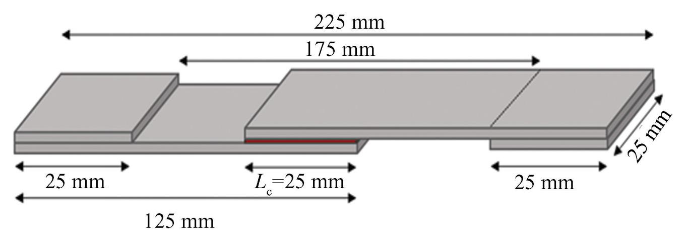
Fig.
1
Base geometric model of single lap joint
This adhesive is widely used in several industrial fields due to its mechanical performance and good resistance to different mechanical stresses.
In a bonded joint,the regions at the free edges of the plate and the adhesive layer are particularly critical as they experience high levels of von Mises,shear and peel stress. To improve the mechanical strength of the adhesive joint and,consequently,the strength of the assembly,geometric modifications are often introduced to these edges. These modifications include plate beveling,adhesive fillets,or a combination of both. These modifications improve the strength of the overlap region by reducing stress concentrations and promoting a more uniform stress distribution across the bonded area.
In practice,such modifications significantly improve fatigue resistance and reduce the risk of premature debonding,enhancing the assembly's overall durability without requiring a change in material. Within this context,geometric modifications were made by varying the overlap length and modifying the shape of the free ends of both plate and adhesive by beveling them in order to assess their effect on the stress distribution of the joint(as shown in Fig. 2).
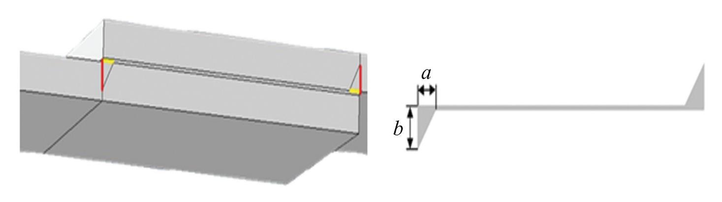
Fig.
2
Modified geometric model
In the modified model,particular attention was given to the free edges of the plate and adhesive layer through combined modifications. This geometric modification involves smoothing the plate profile to minimize the bending effect and reinforcing the adhesive edge to reduce high concentrations of shear and peel stresses.
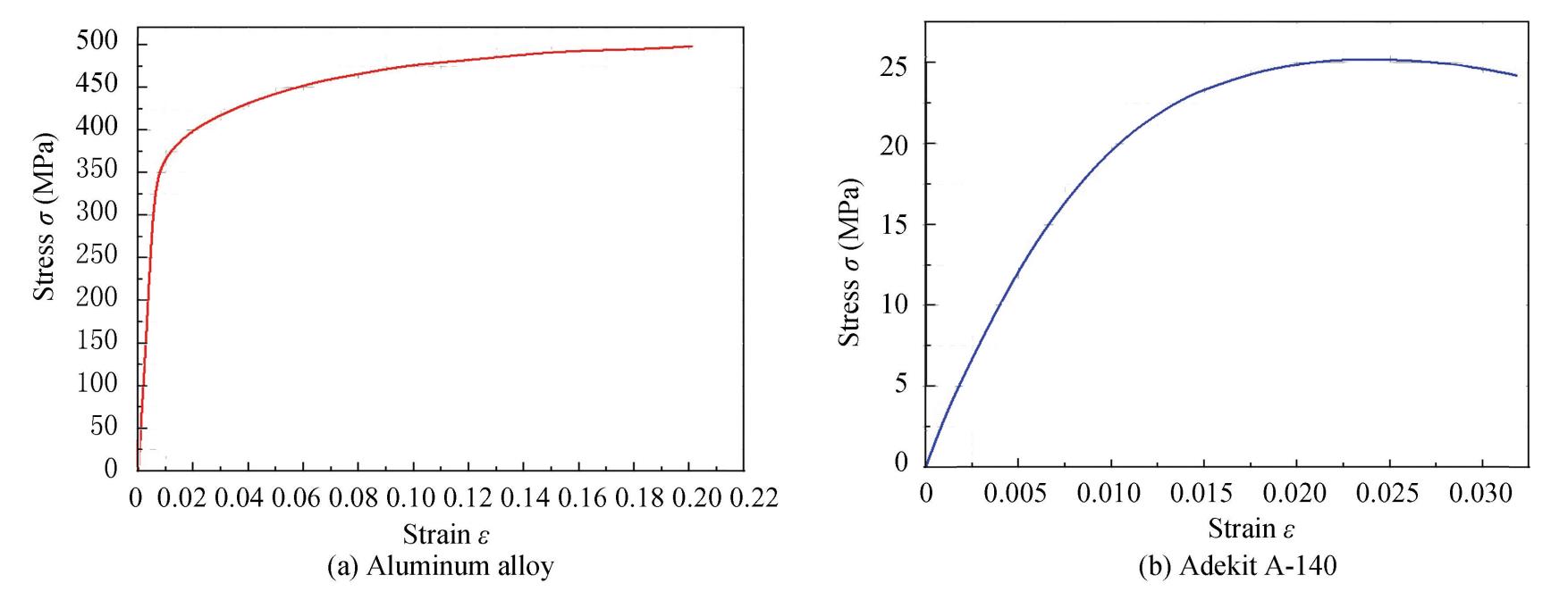
The 2024-T3 aluminum plate and Adekit A-140adhesive were tested in tension,and their stress-strain curves are presented in Fig.3. The mechanical properties of the Adekit A-140 adhesive and Al2024-T3 aluminium alloy are summarized in Table 1. These experimental data were used to define the constitutive behavior of the materials in the Abaqus finite element model.
Table
1
Mechanical properties of Adekit A140 adhesive and Al2024-T3

2 Boundary Condition
To refer to the conditions of the tensile tests carried out on an assembly,one end of one of the two plates was assumed to be embedded,while the other end was subjected to tension with blocking displacement and rotation,as shown in Fig. 4. The boundary conditions applied are typical of tension models for SLJ. The joint is oriented along the x-axis and z is the width direction,while y is the direction perpendicular to the joint plane. Two values of applied stress were considered:10 and 15 MPa.
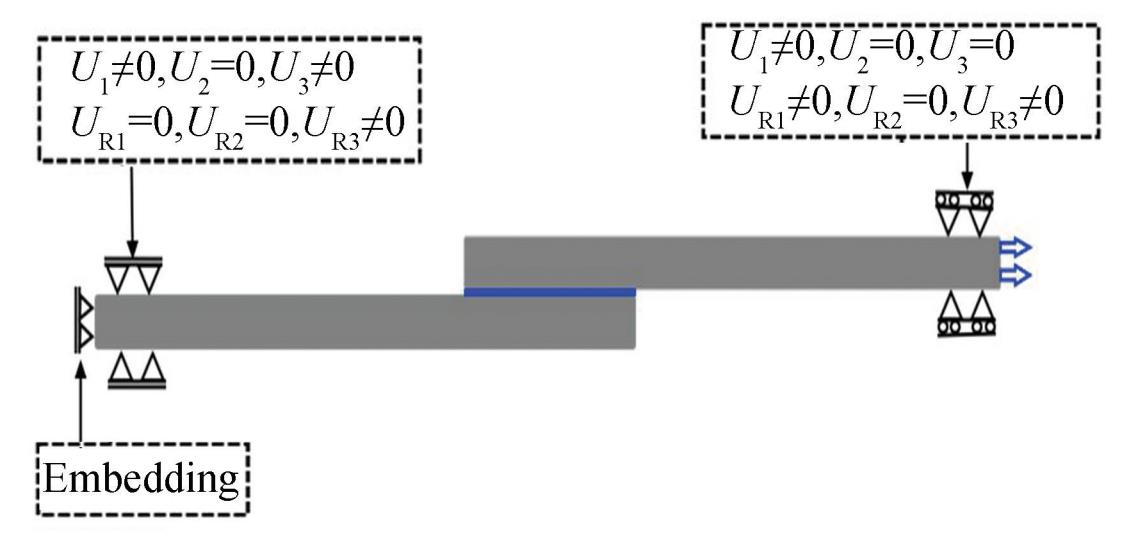
Fig.
4
Boundary conditions
3 Numerical Analysis
The analysis of SLJ was carried out by FEM. The elements of the joint were modelled as three-dimensional bodies which were subsequently meshed using C3D8R type elements. Aluminum and adhesive were represented by a homogeneous,elasto-plastic and isotropic material model. Each overlap substrate was arranged in SLJ with the adhesive layer in the simulation model. To model the bonding connection,surface-to-surface bonding stresses were applied in the contact areas between the overlap and the adhesive.
To ensure the reliability and accuracy of the finite element simulations,a mesh convergence study was carried out before analyzing the different adhesive joint configurations and discussing the results in detail. The present study was conducted on a single lap joint model,to which a uniform stress of 10 MPa was applied along the x-axis. The analysis focused on the maximum value of the von Mises stress in the entire assembly,as well as in the adhesive.
In order to observe the evolution of these stresses,several levels of refinement were tested(as shown in Table 2). As demonstrated in Figs. 5 and 6,the von Mises stress evolution with increasing mesh density reveals a significant variation in the coarse mesh,followed by a stabilization of the results with mesh refinement.
Table
2
Different mesh refinement
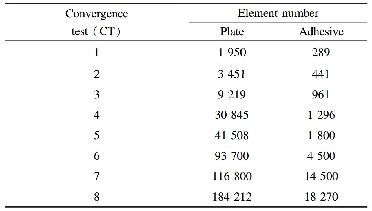
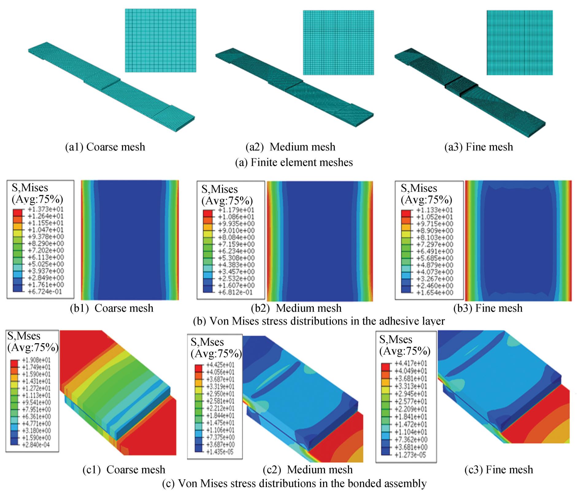
Fig.
5
Mesh refinement effects on the von Mises stress distribution
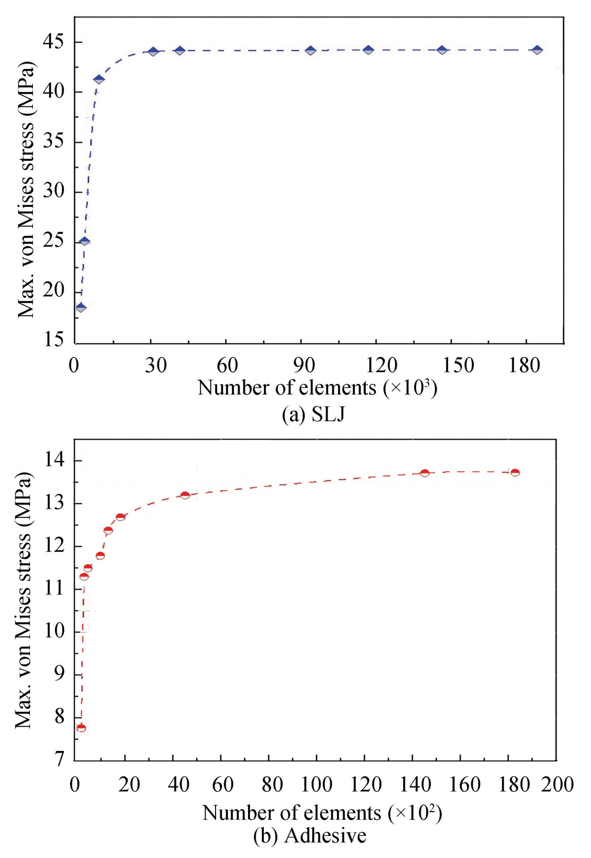
Fig.
6
Maximal von Mises stress as a function of mesh density in SLJ and adhesive
This trend provides further support for the hypothesis that mesh refinement is required,particularly in the overlap region where stress gradient levels are most significant. In order to accurately capture these localized effects,mesh configurations 8were selected,in which a highly refined mesh of0.02 mm was applied to the extremities of the overlap zone,while a moderate refinement of 0. 5 mm was used in the adhesive region and a global mesh of0.7 mm was maintained in the rest of the structure.The number of elements chosen for each material is shown in Table 3.
Table
3
Number of mesh elements for the different materials
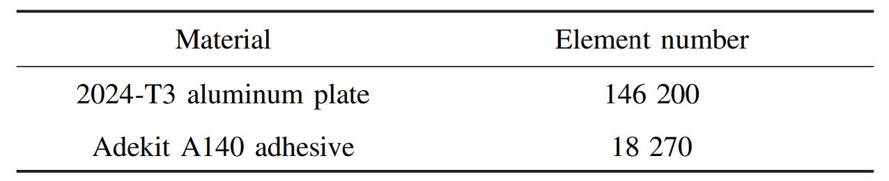
Fig. 7 shows the mesh components with mesh refinement of the overlap area. An attempt has been made to refine the overlap area as much as possible. The two edges have an over-refined mesh where the stress concentration zone is well localized,while the central overlap has a less dense mesh,but it is refined relative to the free part of the plate.
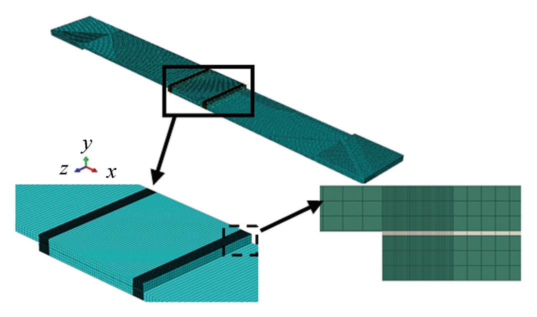
Fig.
7
Mesh representation of the overlap region
The structure was meshed into different zones,with a finer mesh applied to the overlap region. The plate was discretized into three elements through its thickness,while the adhesive was discretized into one element. A graded mesh was used in the overlap area,with the edges of the adhesive and the plate refined more than the central part of the overlap.
The validation of the finite element model was carried out by comparing it with analytical models developed by Goland and Reissner[4]and Volkersen[31](as shown in Fig. 8). The present validation was employed for the purpose of evaluating the shear stress distribution within the adhesive.
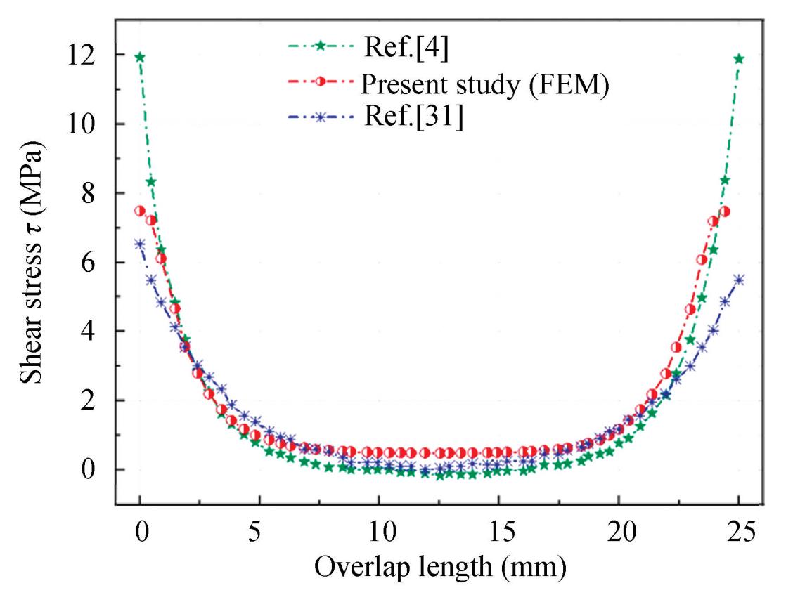
Fig.
8
Shear stress evolution along overlap length:analytical and FEA methods
The results obtained by the numerical modeling method reveal a symmetrical shear stress distribution,with maximum values located at the extremities of the overlap zone. This general tendency is in accordance with the predictions made by the analytical models of Volkersen[31]and Goland and Reissner[4]. However,differences in stress amplitudes persist because the numerical model can incorporate more complex mechanical effects,such as joint bending and multidirectional stresses,whereas analytical models rely on simplifying assumptions.
4 Analysis and Results
4.1 Stress Level in the Adhesive
The von Mises stress levels in the adhesive joint for the two applied stress values are shown in Fig.9.
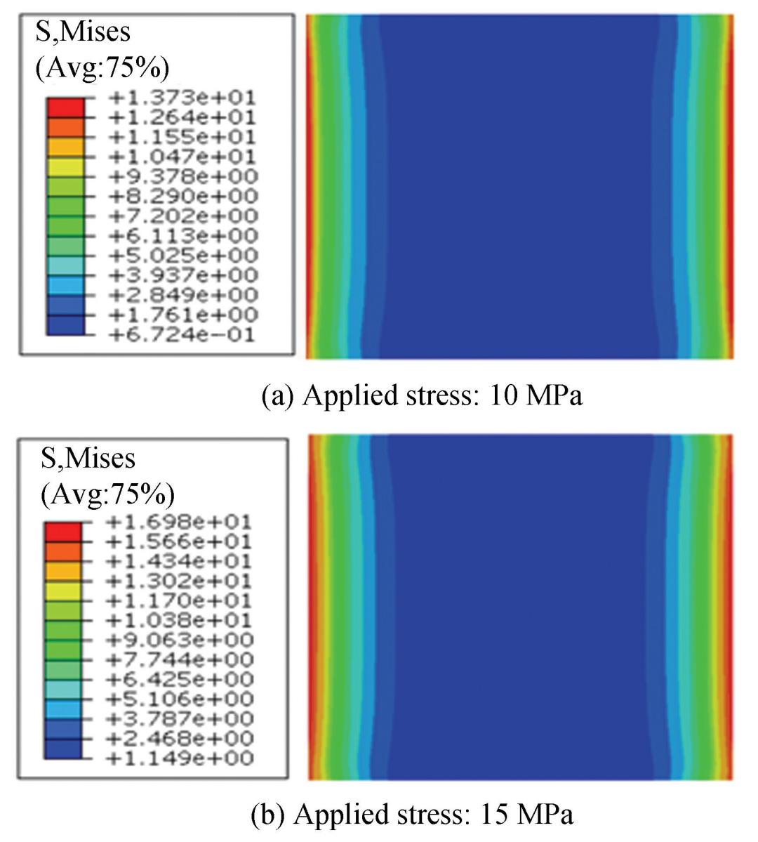
Fig.
9
Von Mises stress level in the adhesive joint for applied stress 10 and 15 MPa (overlap length of 25 mm)
The stress concentration is always at the two edges as the applied stress increases. At 15 MPa of applied stress,the von Mises stress in the adhesive joint largely exceeds the elastic limit of the material. The same behavior of the adhesive is observed for both values of applied stress when the overlap length is increased to 40 mm(as shown in Fig.10). The von Mises stress value is slightly lower than in the case of25 mm of adhesive length.
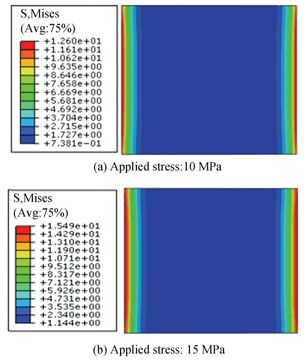
Fig.
10
Von Mises stress level in the adhesive joint for applied stress 10 and 15 MPa (overlap length of 40 mm)
The zone of high stress concentration is very small and is located at the two free edges of the adhesive layer. As the applied stress increases,this zone expands slightly and exhibits higher values than in the case of an applied stress of 10 MPa. The core of the adhesive remains inactive with lower von Mises stress values in both overlap lengths and for both applied stress levels.
4.2 Modification of the Edges of the Adhesive and the Plate
For this part,in order to minimize the stress concentration in the adhesive joint,we tried to fix the parameter a and modify the edges b of the adhesive and the two adherends(as shown in Fig.2).
The variation of parameter a is designed to increase the quantity of adhesive at the edge,while the variation of parameter b aims to minimize or redistribute the zone of high stress concentration within the adhesive joint.
4.2.1 Modification of the overlap length of 25 mm
1)Von Mises stress. Stress analysis of the adhesive joint with internal beveling of the plate and adhesive bead modifications shows a similar von Mises stress distribution for a 25 mm overlap without modification(as shown in Fig.11). High stress concentrations remain at the edges,particularly in the modified zones,while the adhesive core remains inactive. The maximum stress depends on the edge modification parameter b,but these changes do not improve joint resistance and significantly increase von Mises stress.
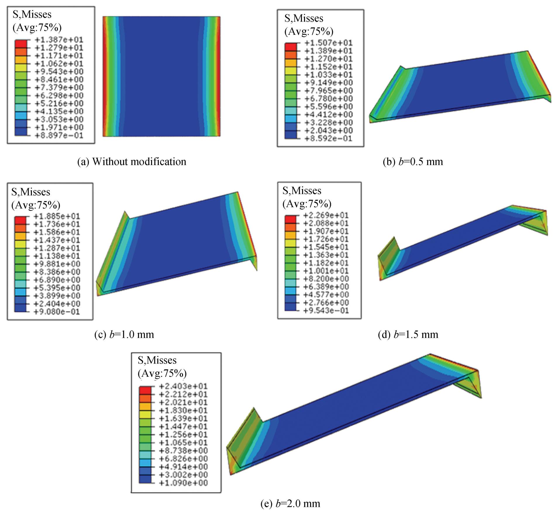
Fig.
11
Von Mises stress level in the adhesive joint (25 mm overlap length and applied stress 10 MPa)
Increasing the b dimension results in greater stress concentration and a larger affected zone,which is distributed along the height. For an overlap length of 25 mm,internal beveling of the plate ensures a minimal b height,which guarantees that the adhesive quantity on the chosen side a transfers only minor stresses,providing a relatively homogeneous surface with high stress concentration at the two adhesive edges. However,when b approaches the plate thickness,significant stress concentration occurs,creating a high-stress zone in the upper part of the adhesive where only a small quantity of adhesive is present.
For the peel stress level in the adhesive,the proposed modifications to the shape of the adhesive and plate edges lead to an increase in the stress value,except in the case of a modification with a length b equal to 0.5 mm where the peel stress is significantly reduced compared to the case without modification,as shown in Fig.12. The area of high stress concentration changes location compared to the unmodified case.
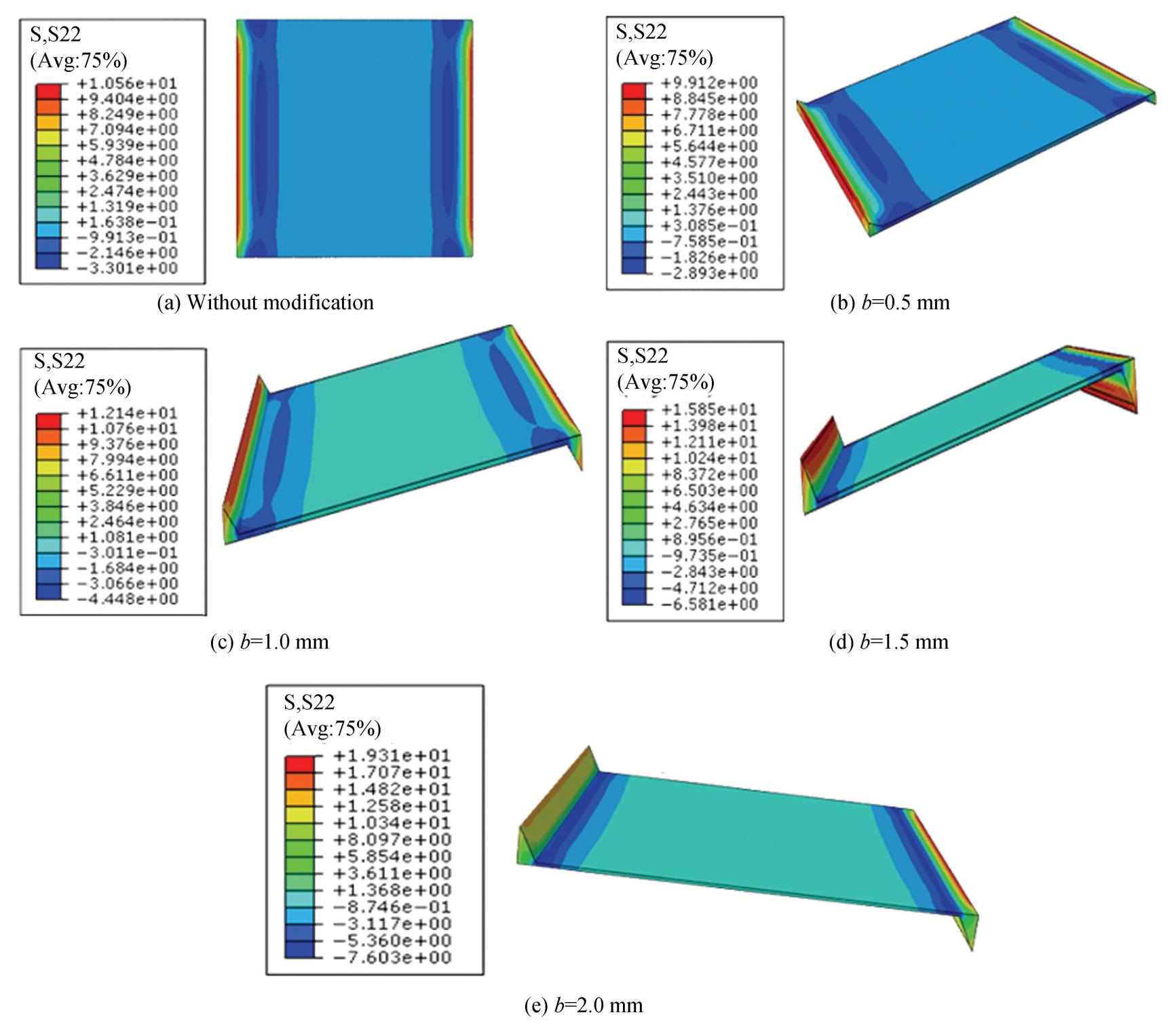
Fig.
12
Peel stress level in the adhesive joint (25 mm length and 10 MPa)
2)Peeling stress. Similar to the von Mises stress level,variation in the adhesive fillet height b generates significant tensile stresses in regions with less adhesive material. Consequently,the adhesive is mainly solicited in the modified part. On the other hand,the compressive zone in the adhesive layer becomes increasingly pronounced in the unmodified region,leading to a higher compressive stress value that can reach almost twice that observed in the case of an unmodified adhesive joint.
The increase of the applied stress causes an excessive increase in the value of von Mises and peel stress in the adhesive layer(as shown in Figs.13 and14),which easily reaches the value of the adhesive's breaking limit. On the other hand,the size of the high stress concentration area becomes increasingly large,and for the peel stress,the active surface of the adhesive becomes larger.
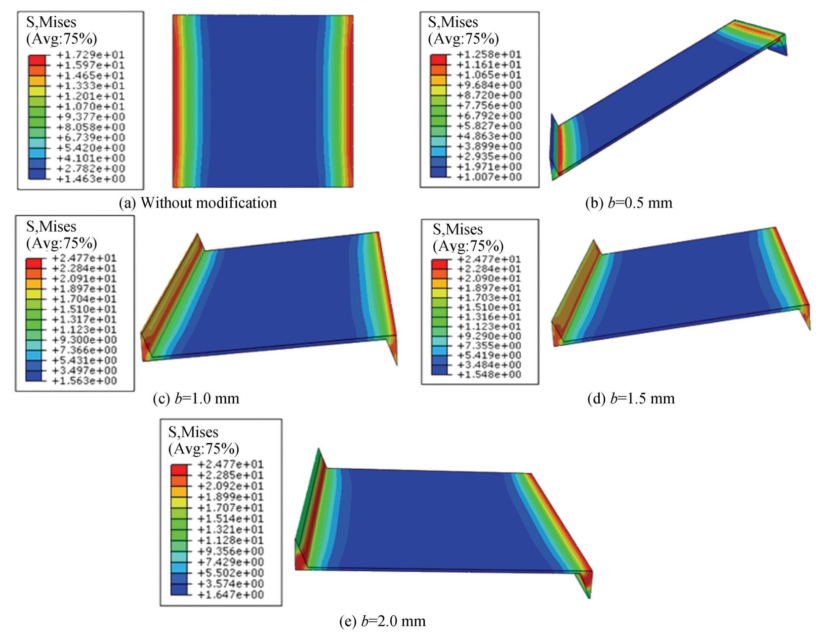
Fig.
13
Von Mises stress level in the adhesive joint (25 mm length and 15 MPa)
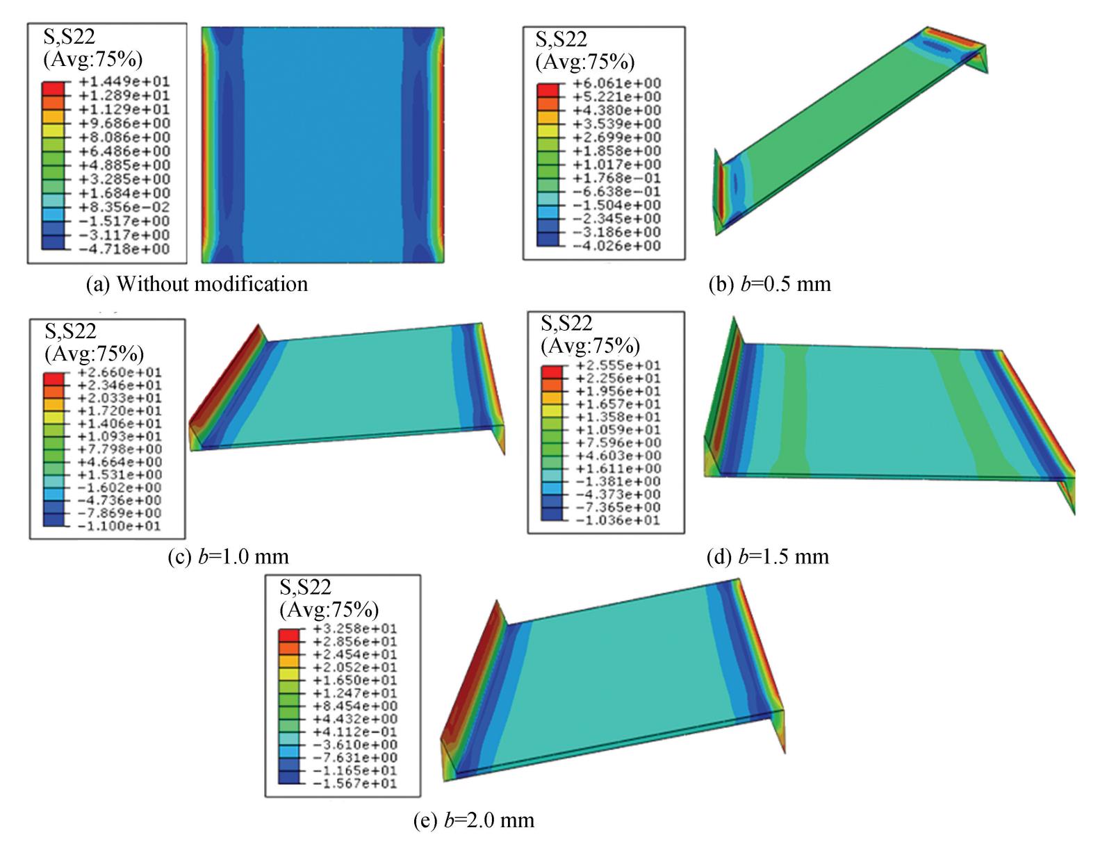
Fig.
14
Peel stress level in the adhesive joint (25 mm length and 15 MPa)
4.2.2 Applied load 15 MPa
The increase in the applied stress rapidly leads to deterioration of the adhesive layer depending on the selected fillet height b. For the chosen fillet parameter a and an overlap length of 25 mm,it is preferable to adopt a minimal height b in order to obtain an optimal adhesive fillet surface that ensures reliable joint resistance against the applied load. Increasing the height b reduces the adhesive quantity at the joint edges and results in poor resistance due to assembly bending,where significant moments are concentrated at the plate edges. The stress concentration zone then becomes more pronounced compared to the case of a10 MPa applied stress,producing von Mises stress values that can quickly damage the adhesive layer.Likewise,increasing the fillet height b leads to higher compressive stress concentrations,localized in more marked regions along the adhesive surface(as shown in Fig.14).
4.2.3 Overlap length effect
In order to see the effect of these geometrical modifications of the two substrates(internal beveling of the plate and adhesive bead)in relation to the adhesive overlap length,a length of 40 mm was chosen.
Unlike the 25 mm overlap length,where the modifications did not result in a reduction of the various stresses in the adhesive joint and caused a more significant high stress concentration zone,the40 mm overlap length reduces the values of the various stresses in the adhesive joint without even making the proposed modifications(as shown in Fig.15). With the modifications of the edges of the two plates and the adhesive bead,a significant reduction of the von Mises stresses can be observed,which can reach up to 30% and the high stress concentration zone is greatly reduced. Similarly,an overlap length of 40 mm,with the various modifications made to the edges of the two substrates results in a significant reduction in the peel stress in the adhesive joint of more than 50%(as shown in Fig.16). If the applied stress is increased,the value of the von Mises stress increases slightly compared with the case of an applied stress of 10 MPa(as shown in Fig.17). The modifications made to the two edges of components provide a significant reduction in the value of the von Mises stress,especially in areas of high stress concentration.
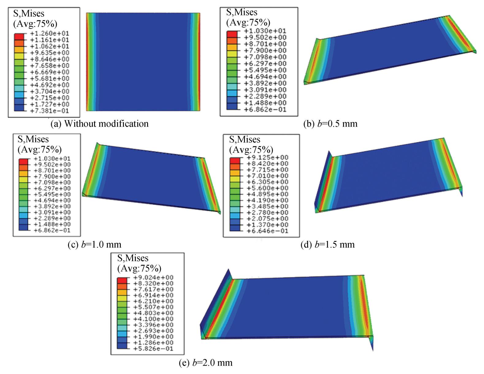
Fig.
15
Von Mises stress level in the adhesive joint (40 mm length and 10 MPa)
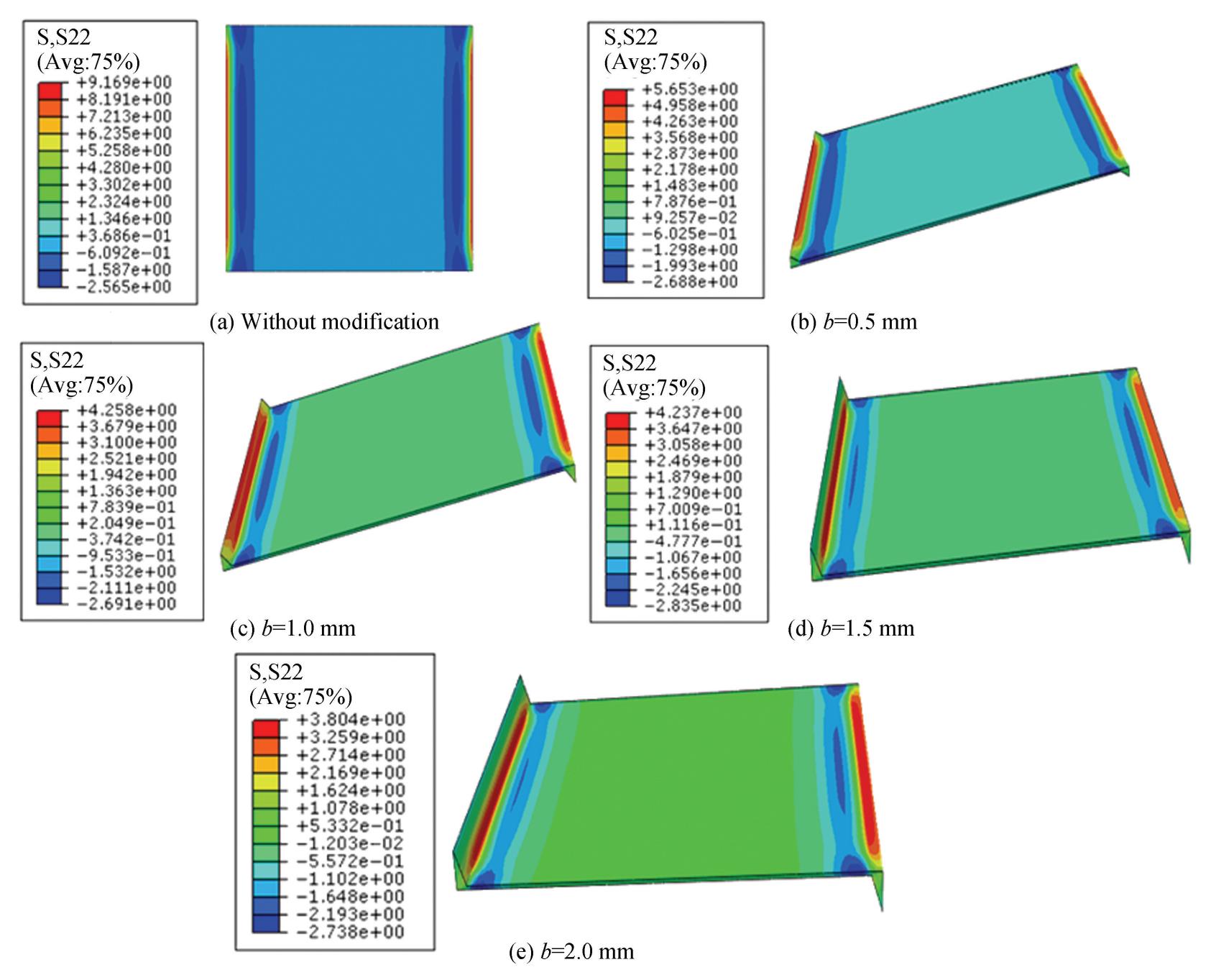
Fig.
16
Peel stress level in the adhesive joint (40 mm overlap length and 10 MPa)
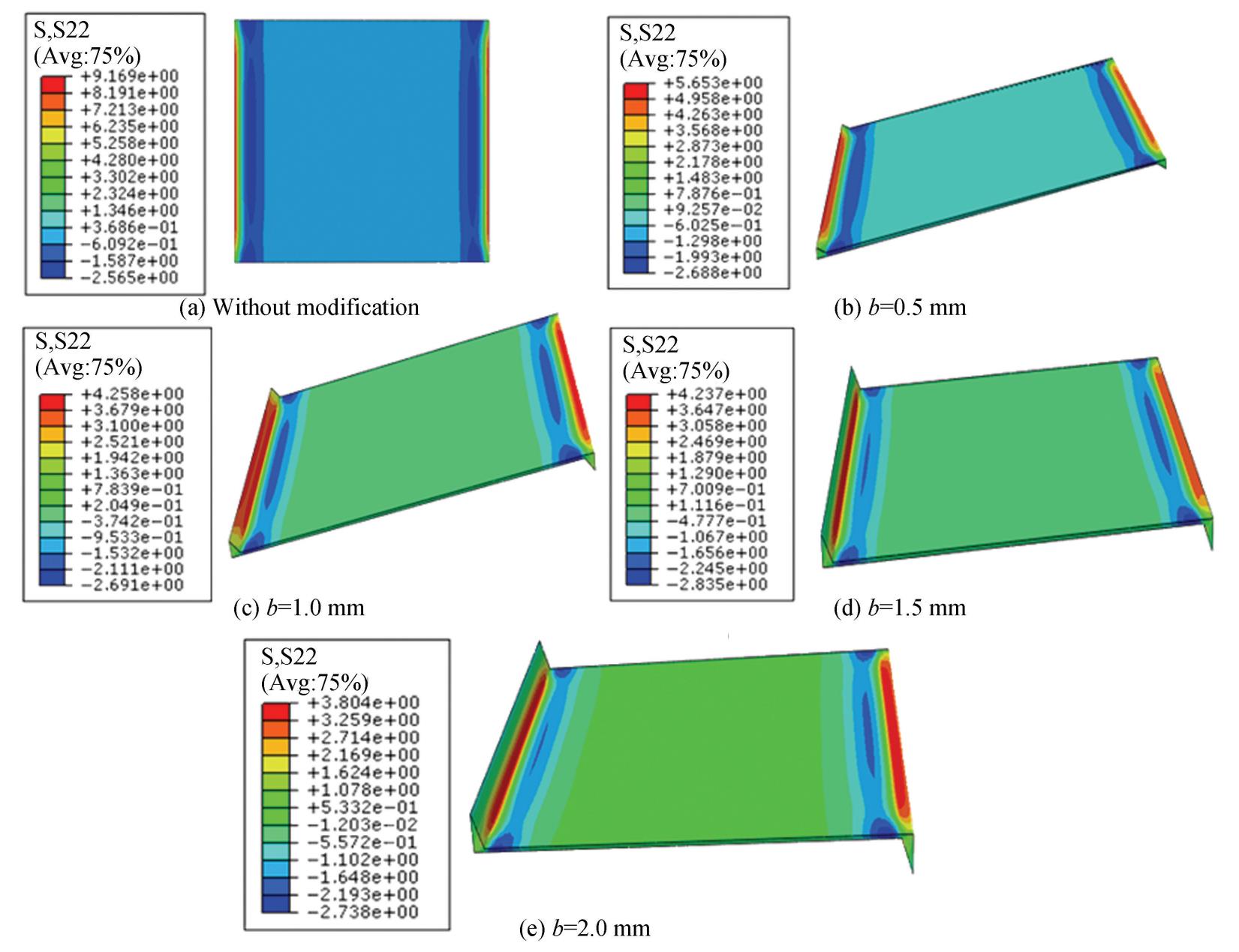
Fig.
17
Von Mises stress level in the adhesive joint (40 mm overlap length and 15 MPa)
For a given fillet length a and overlap length,varying the fillet height b in the adhesive layer provides a greater reduction in stresses while minimizing the bending effect. This is because the bending moment at the overlap edges becomes negligible due to the larger effective bonding area.The region of high stress concentration remains similar to that of the unmodified case.
Regarding peel stresses,varying the fillet height reduces the peak tensile and compressive stresses.These values are lower than those obtained for an overlap length of 25 mm,and remain well below the elastic limit of the material.
Increasing the applied stress does not affect the selected fillet parameters,resulting in low von Mises stress values in the adhesive layer that remain well below its elastic limit. Variation in the fillet height b results in lower stress levels under higher applied loads,with the adhesive layer exhibiting better resistance than in the unmodified case.
For peel stress,increasing the applied load leads to higher stress values in the adhesive joint(as shown in Fig. 18). However,geometric modifications to the adhesive and plate edges significantly reduce peel stress. When the edge modifications are significant,peel stress is reduced by more than half.
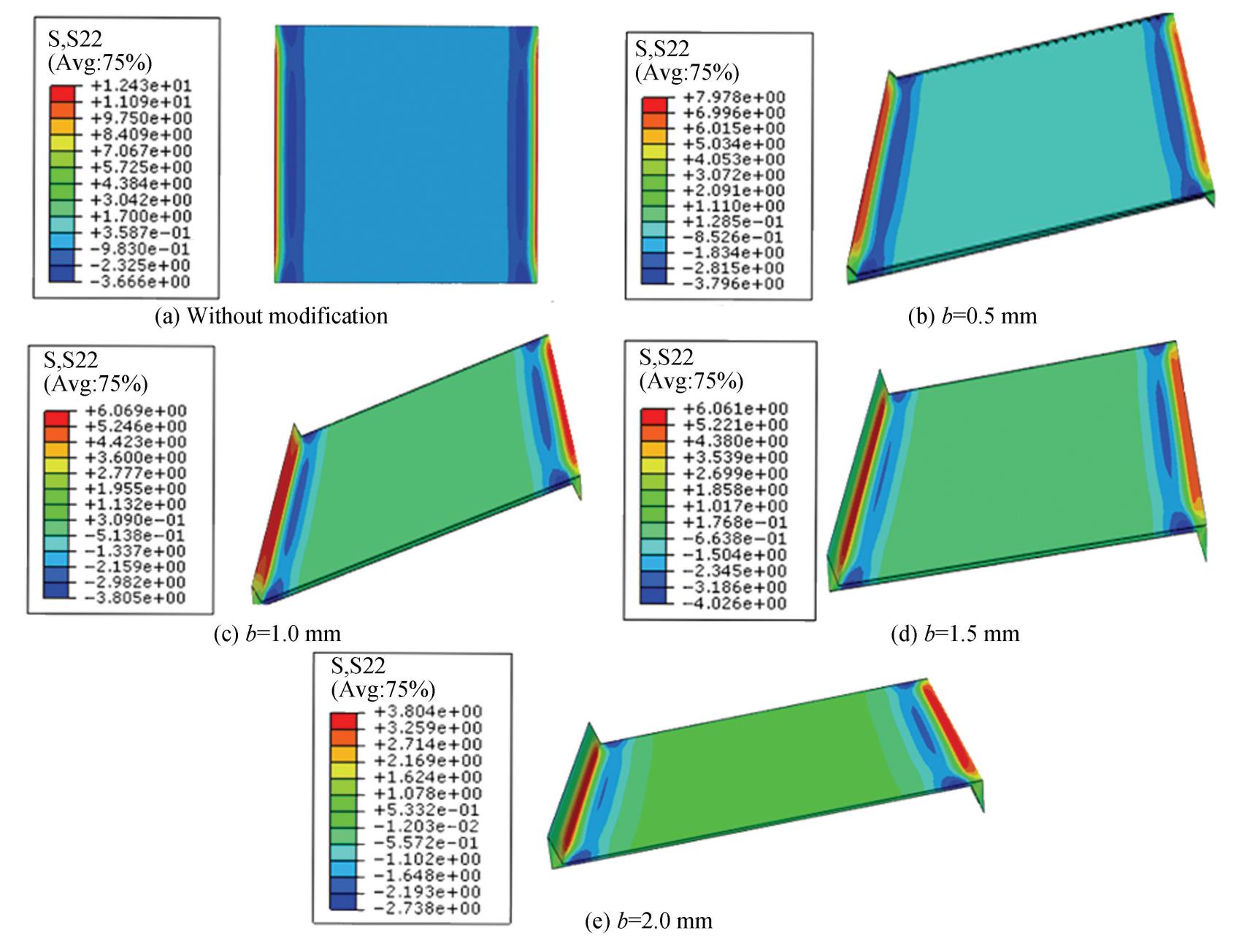
Fig.
18
Peel stress level in the adhesive joint (40 mm overlap length and 15 MPa)
The variation of the fillet height b clearly reduces the concentration of peel stresses and ensures an almost similar distribution of tensile and compressive stresses as in the unmodified case. A larger fillet height b,combined with an overlap length of 40 mm,improves the mechanical behavior of the adhesive joint.
4.3 Stress Distributions in Adhesive Joint
It can clearly be seen that the stress concentration is at the two edges of the adhesive while the core is inactive,as shown in Fig.19. The von Mises stress at the edges increases by almost 4 MPa when we increase the applied stress. The adhesive core becomes active with a small increase in the von Mises stress value. For the peel stresses,increasing the value of the applied stress results in an increase of almost4 MPa at both edges,and near these edges,the compressive stresses become significant. While the core of the adhesive remains inactive.
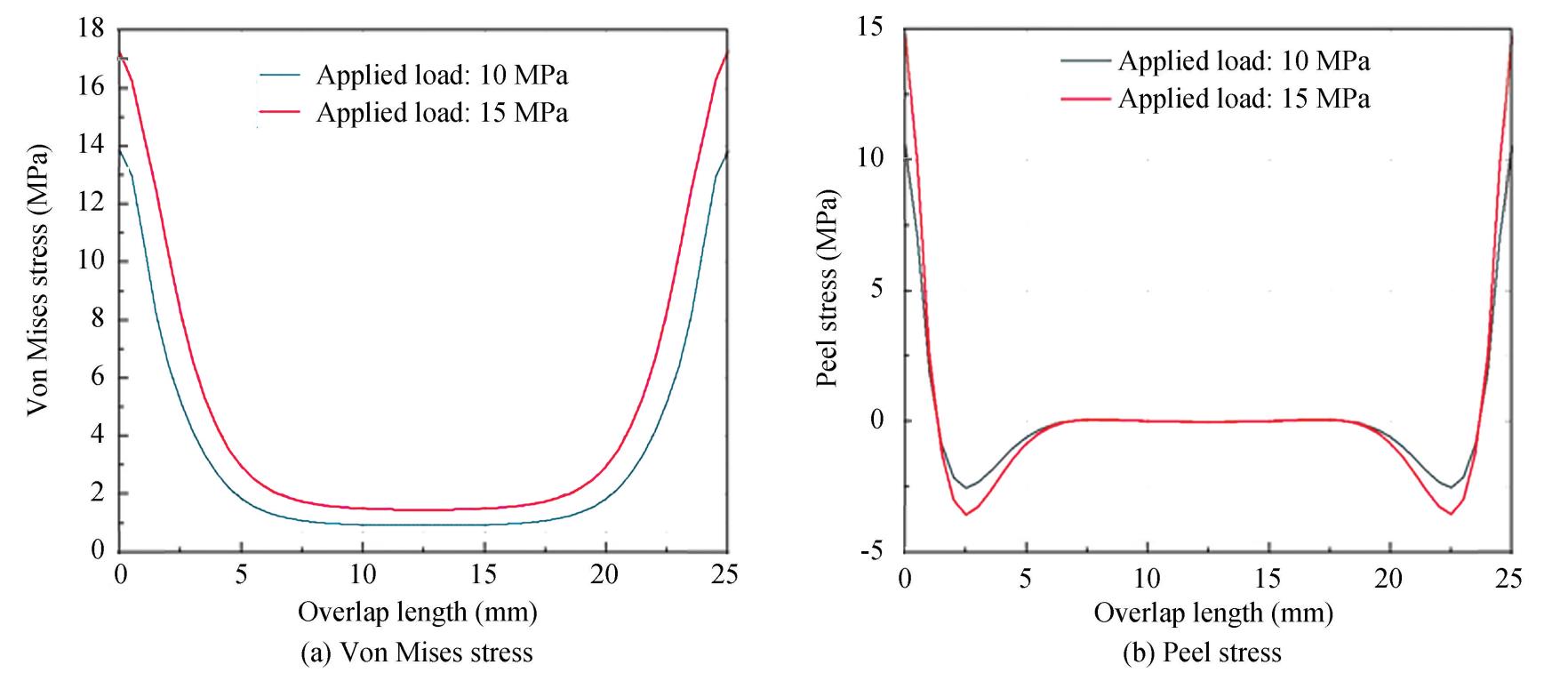
Fig.
19
Stress variation of von Mises and peel along the overlap length for two applied stresses Overlap Length Effect
To reduce these stresses in the adhesive joint,one solution is to increase the overlap length. A length of 40 mm was chosen for this purpose. The variation of the different stresses is shown in Fig.20.
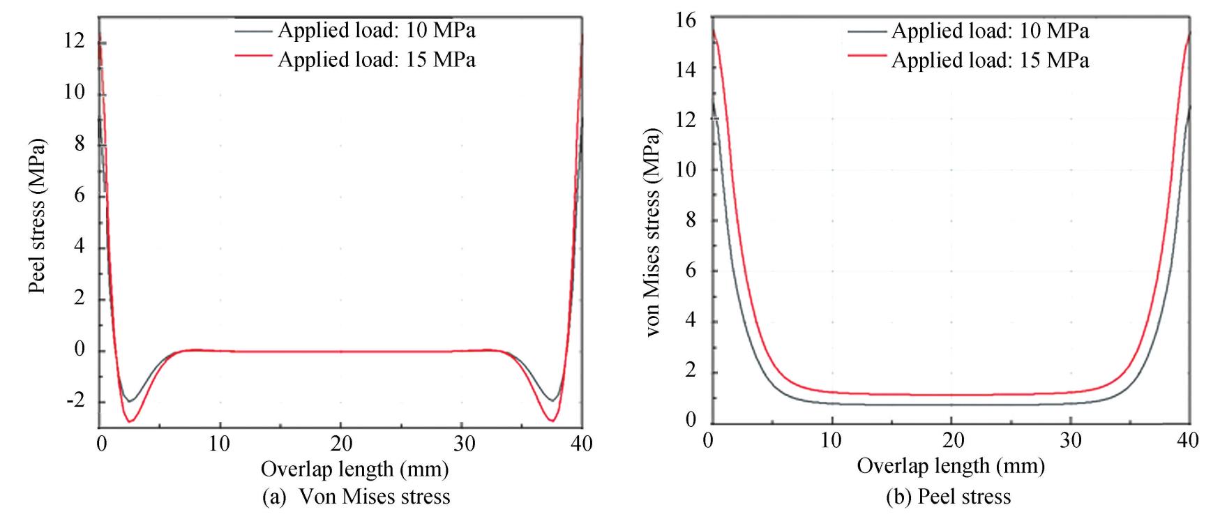
Fig.
20
Stress variation of von Mises and peel along the overlap length for two applied stresses
By increasing the overlap length,the various stresses in the adhesive joint at both edges are slightly reduced,with this reduction varying from 2 MPa for the von Mises and peel stresses. The increase in applied stress leads to an increase in the various stresses,but they remain lower than in the case of the25 mm overlap. At longer overlap lengths,the adhesive core remains inactive.
4.4 Effect of Edge Modification of the Adhesive and the Adherent
A second solution to reduce stress in the adhesive joint is to modify the two edges by beading the adhesive and/ or beveling the plates. Our modification is to have both a bevel and a bead simultaneously by varying the parameter b. The analysis of the different stresses in the joint is shown in Fig.21.
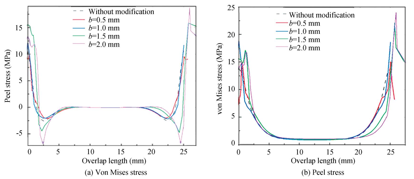
Fig.
21
Variation in von Mises stress and peel stress as a function of overlap length for stresses applied at10 MPa after modifications to both edges of the adhesive
It is noticeable that the modifications are made to the two edges of the adhesive and the substrates.There is a reduction in the various stresses only when b equals 0.5 mm. If the distance b is increased,the behavior is reversed,and the stresses at both edges of the adhesive increase considerably. The stresses exceed the adhesive's elastic limit. The modification also leads to a significant increase in the peel stresses,especially near the two edges where compressive stresses are high.With all the modifications made,the core of the adhesive remains virtually inactive. On the other hand,a stress peak is observed at the edges of the adhesive. If we increase the value of the applied stress to 15 MPa.The same observation was made:an excessive increase in the value of the von Mises stress at the edges of the adhesive was observed(as shown in Fig.22).
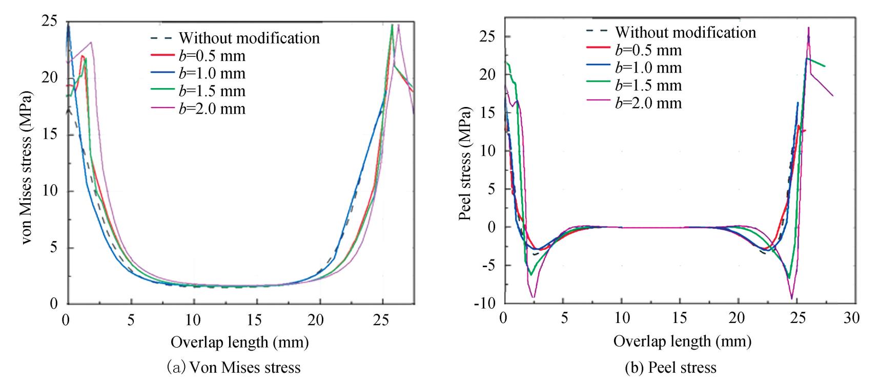
Fig.
22
Variation in von Mises stress and peel stress as a function of overlap length for stresses applied at15 MPa after modifications to both edges of the adhesive
Based on the von Mises and peel stress results for the two applied loads of 10 and 15 MPa,it is clear that an adhesive fillet increases the effective overlap length as the fillet b increases. However,the bending effect becomes significant at this overlap length since the region between the toe and the overlap length is relatively large,which can easily cause joint rotation due to the nonlinearity of the two forces. This generates a considerable bending moment and,consequently,high stresses in the adhesive layer.
On the other hand,unlike the case of an adhesive fillet combined with an external beveling of the plate edges,the plate edge is not sufficiently protected and may induce a rapid debonding at this location under high applied loads,especially when the fillet b becomes large compared to the plate thickness.
4.5 Effect of Overlap Length on Edge Modification
In contrast to the 25 mm overlap length,von Mises stress drops considerably if the 40 mm overlap length is increased and modifications are made to both edges of the adhesive and the two substrates. It can be clearly seen that this modification considerably reduces the value of von Mises stress and peel stress for the different values of the geometric parameters(see Fig.23).
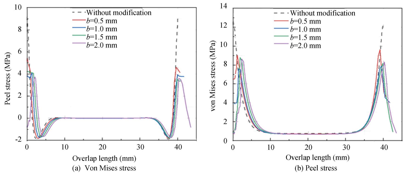
Fig.
23
Variation in von Mises stress and peel stress along the overlap length for an applied stress of10 MPa as a function of different values of the b parameter
The different stress values decrease as the value of b increases. A reduction of more than 4 MPa in von Mises stress and more than 5 MPa in peeling stress is observed. When the applied stress value is increased to 15 MPa. The various stresses in the adhesive increase. With the modifications made to the two edges of the two substrates,these stresses are significantly reduced but remain high compared to the case where the applied stress is 10 MPa(as shown in Fig.24). Increasing the geometric parameter b reduces von Mises stress by more than 4 MPa and the peel stress by more than 9 MPa.
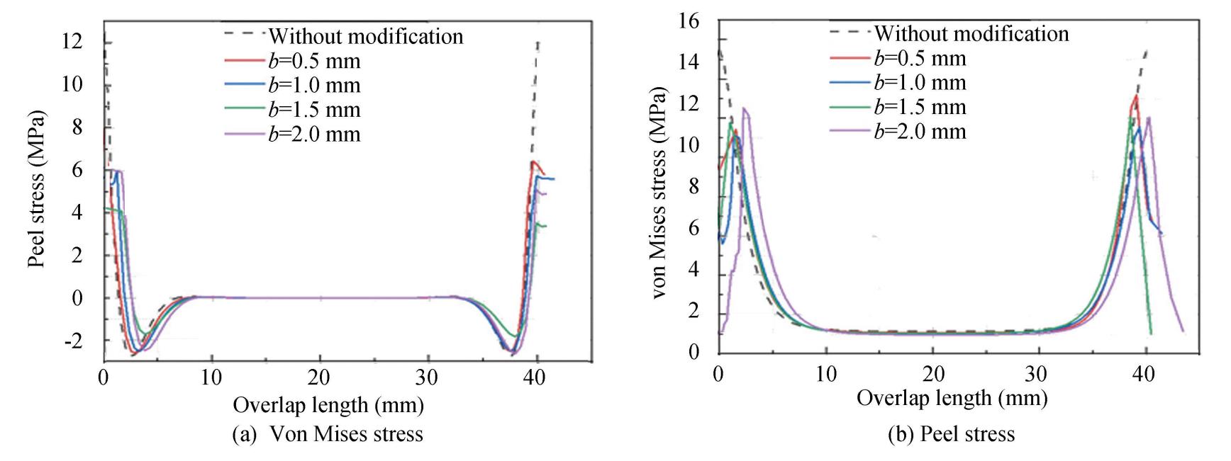
Fig.
24
Variation in von Mises stress and peel stress along the overlap length for an applied stress of15 MPa as a function of different values of the b parameter
According to the stress variations shown in Figs.23 and 24,the presence of an adhesive fillet,combined with the internal beveling of the plate edges,significantly reduces stresses in the adhesive layer,particularly when the overlap length is large(40 mm). At this overlap length,the portion of the plate between the toes and the overlap region is relatively short compared to the overlap itself. This prevents bending induced by the nonlinearity of the two forces. Consequently,the effect of the bending moment is greatly reduced. In fact,increasing the fillet height b improves the stress distribution values in both the central region and the modified area.
4.6 Comparative Analysis
The effect of varying the height b at the internal bevel of the plate on von Mises and peel stresses was evaluated for two overlap lengths(25 mm and40 mm)under different applied stresses(as shown in Fig.25).
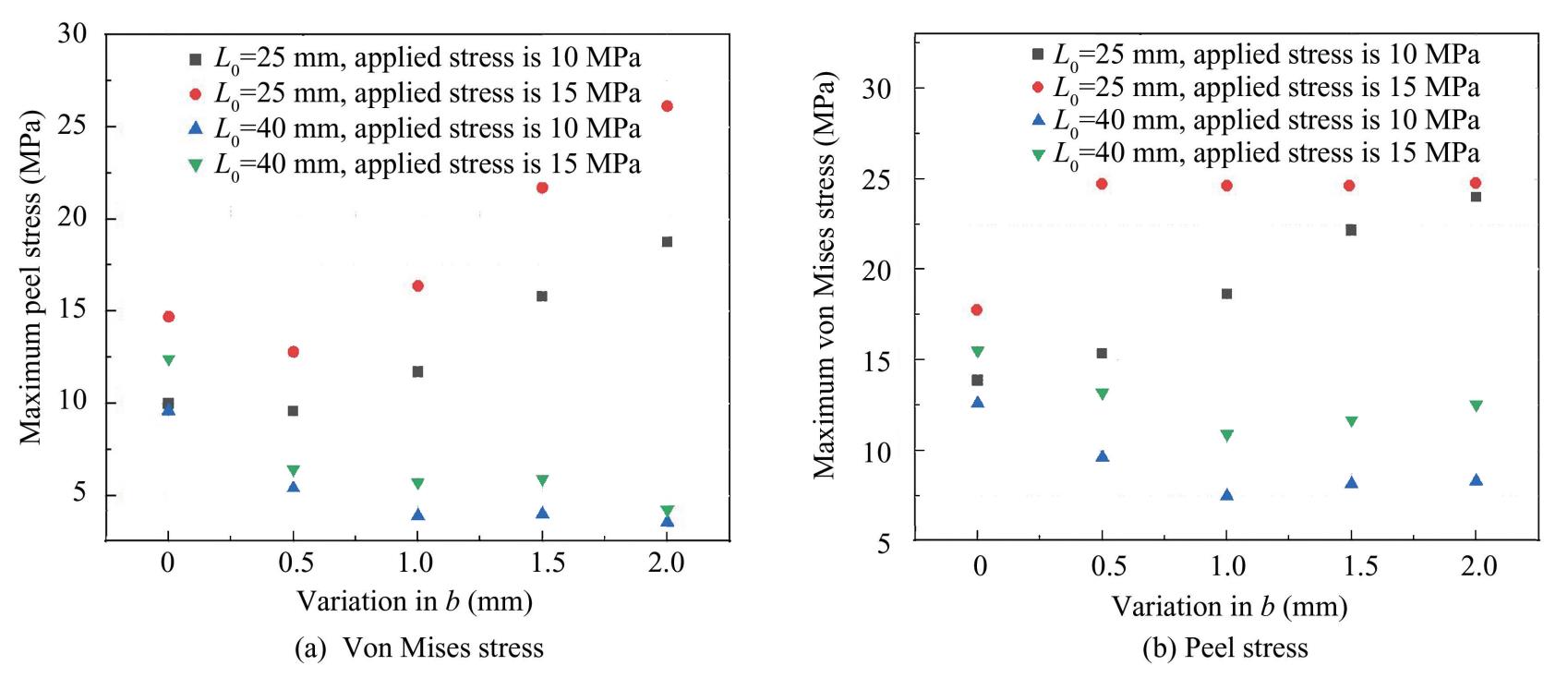
Fig.
25
Effect of the variation in bevel height b on von Mises stress and peel stress for different overlap lengths and applied stress levels
Without modification,a 40 mm overlap improves joint strength by minimizing stress transfer into the adhesive layer,with von Mises stress at15 MPa similar to that of a 25 mm overlap under the same stress. For a 25 mm overlap,varying b significantly reduces adhesive strength,causing high stress concentrations that reach the breaking limit of15 MPa. At 10 MPa,von Mises stress increases notably with b. For a 40 mm overlap,varying b enhances joint strength by reducing von Mises stress.
For peel stress(as shown in Fig.25(b)),a smaller overlap(25 mm)results in significant peel stress,often exceeding its elastic limit and increasing with b,potentially leading to failure. However,with a larger bonding surface(40 mm),peel stress remains well below the adhesive's elastic limit and decreases with b.
5 Conclusions
The study aimed to analyze the influence of the geometric parameters of the assembly,namely the overlap length,the applied stress,and the geometric variation of the two edges of the substrates,by highlighting an internal beveling of the plate with an adhesive bead,on the performance of an SLJ. The results showed the effectiveness of the finite element method for the analysis of the resistance of the assembly by evaluating von Mises shear and peel stresses in the adhesive joint as a function of different geometric parameters. The analysis shows that the von Mises and peel stresses in the adhesive joint are always concentrated at its two free edges,regardless of the applied stress or overlap length. Increasing the applied stress can produce high stresses in the adhesive that easily exceed its elastic limit and approach failure,particularly at shorter overlap lengths. Conversely,increasing the overlap length significantly reduces these stresses,keeping them below the elastic limit of the adhesive even at high applied loads. Modifications to the edges of the substrates and the adhesive further increase the strength of the bond,particularly at greater overlap lengths,resulting in a significant reduction in stress concentrations.
The variation of the adhesive fillet b should be considered together with the fillet width a in order to further optimize the modification of the adhesive and plate edges. For small overlap lengths,the value of the fillet b should be minimized to prevent plate detachment caused by a significant bending moment under high applied stress. For large overlap lengths,the bonding surface provides sufficient strength for a good joint and considerably reduces the bending effect. Consequently,variation in fillet height b does not significantly affect the stress reduction rate within the adhesive layer.
Further optimization is necessary to reduce stresses in the modified region by varying the fillet width and considering a non-symmetric joint(composite-aluminum).
Conflicts of Interest
The authors declare no potential conflicts of interest.
