Abstract
This study reports the electrochemical synthesis of nanocomposite thin films composed of polyaniline (PANI) and copper oxide (CuO) deposited on Indium Tin Oxide (ITO)-coated glass substrates. The films were prepared via in-situ electropolymerization of aniline in the presence of CuO nanoparticles, followed by detailed structural, morphological, and electrochemical characterization. Scanning Electron Microscopy (SEM) revealed a uniform nanofibrillar morphology of PANI decorated with well-dispersed CuO nanoparticles. Electrochemical impedance spectroscopy demonstrated a dramatic reduction in charge-transfer resistance, with the ITO/PANI-CuO electrode achieving ~80 Ω·cm2 compared to ~3 000 Ω·cm2 for ITO/PANI and ~1 000 Ω·cm2 for ITO/CuO. Cyclic voltammetry confirmed the superior pseudocapacitive behavior of the hybrid electrode, with an areal capacitance of ~0.548 F/cm2, representing an enhancement of over two orders of magnitude relative to pristine PANI (~0.004 27 F/cm2). These findings highlight the strong synergistic effect between PANI and CuO, confirming the potential of the nanocomposite films as high-performance electrodes for supercapacitor applications.
Keywords
0 Introduction
Nanotechnology has emerged as a key pillar of modern scientific and technological innovation. As a highly interdisciplinary field, it holds transformative potential across diverse sectors, including electronics[1–3], energy[4-5], healthcare[6-7], and environmental science[8-9]. By leveraging the unique properties of matter at the nanoscale, nanotechnology enables the development of advanced smart materials that outperform their bulk counterparts in terms of functionality and efficiency[10].
Nanomaterials, typically defined by dimensions ranging from 1 to 100 nm[11], exhibit distinct physical, chemical, optical, and electronic characteristics that open the door to a wide range of innovative applications[12-13]. Among these, nanocomposites formed by combining conductive polymers with inorganic nanoparticles have garnered increasing attention due to the remarkable synergy between their constituents[14-15].
These hybrid materials offer a unique combination of mechanical flexibility, electrical conductivity, and chemical stability, making them highly suitable for applications such as flexible electronics[16], smart sensors[17-18], energy storage devices[19-20], and catalysis[21–23].
Polyaniline(PANI) is one of the most promising conductive polymers owing to its high electrical conductivity, chemical and thermal stability, low cost, and ease of synthesis[24-26]. Its redox-active nature, characterized by reversible transitions between benzenoid and quinoid structures[27], contributes to its excellent electrochemical responsiveness[28]. Among the available synthesis methods, electropolymerization is particularly attractive for producing thin[29], uniform PANI films on conductive substrates with controllable morphology and thickness.
Copper oxide(CuO), on the other hand, is a p-type semiconductor known for its thermal stability, interesting photoactive behavior, and high catalytic potential[30-31]. At the nanoscale, CuO nanoparticles have demonstrated the ability to significantly enhance the electrochemical and optical properties of polymer-based composites[32-33].
When integrated into a PANI matrix, CuO nanoparticles can improve doping levels, boost redox activity, and provide synergistic effects that result in multifunctional nanocomposites with superior electrochemical performance[34-35].Recent global research has reported significant progress on PANI-based nanocomposites with metal oxides such as NiO and MnO2, which have demonstrated specific capacitances of 522.5 F/g(PANI–NiO, 79.5% retention after 3 000 cycles)[36] and 417 F/g(PANI-MnO2, scan rate 5 mV/s)[37]. More complex hybrids, such as PANI-CuO-GO, achieved even higher capacitance(~595 F/g) with excellent cyclic stability(~95.8% retention)[38].The conductive polymer-metal oxide synergy underlying these systems has been thoroughly reviewed recently[39]. However, most PANI-CuO systems so far employ chemical or hydrothermal synthesis, which often lack film uniformity and direct electrode integration. In contrast, our study uses in-situ electropolymerization on ITO, enabling homogeneous compositing and scalable thin-film fabrication.
In this context, the present work aims to synthesize PANI/CuO nanostructured thin films via electropolymerization, using Indium Tin Oxide(ITO) glass as a conductive substrate in an acidic environment favorable for aniline polymerization. This strategy not only allows precise control over the PANI thin film growth but also enables the effective incorporation of CuO nanoparticles into the polymer matrix, resulting in a homogeneous and functional nanostructure.
The ultimate goal of this study is to develop and evaluate high-performance thin-film electrodes for supercapacitor applications. The electrochemical behavior of the synthesized thin films is investigated using cyclic voltammetry to assess their ability to store and release electrical energy rapidly and efficiently. This work contributes to the growing field of nanostructured materials for energy storage by exploring a cost-effective and scalable route to multifunctional, conductive polymer-based composites.
1 Details
1.1 Chemicals
All aqueous solutions and chemical reactions were carried out using distilled(DI) water to prevent any contamination that could alter the properties of the synthesized materials. Analytical-grade reagents, including CuO(size<50 nm), sulfuric acid(H2SO4), nitric acid(HNO3), aniline(C6H7N), anhydrous sodium sulfate(Na2SO4), acetone(C3H6O), ethanol(C2H3OH), and potassium chloride(KCl), were purchased from Sigma-Aldrich. A 0.1 mol/L KCl solution was freshly prepared in the laboratory.
ITO-coated glass substrates with a thickness of 1 μm and surface resistivity of 30 Ω/sq were provided by Solems Company(France). Electrochemical experiments and thin film deposition were performed using a conventional three-electrode electrochemical cell configuration. The ITO substrate served as the working electrode, an Ag/AgCl electrode as the reference electrode, and platinum(Pt) as the counter electrode.
1.2 Substrate Surface Preparation
ITO-coated glass substrates(10 mm×10 mm, thickness=1 μm, sheet resistance=30 Ω/sq, provided by Solems, France) were cleaned prior to deposition using an ultrasonic bath to ensure surface cleanliness and eliminate defects. The cleaning process involved sequential sonication in distilled water, acetone, and ethanol—each for 10 min—followed by thorough rinsing with distilled water and drying at room temperature, as shown in Fig.1.
1.3 Instrumentation
Electrochemical measurements were carried out using a VersaSTAT 3 potentiostat/galvanostat controlled by VersaStudio software at room temperature, as shown in Fig.2. A three-electrode glass cell(PYREX, 200 mL) with a PTFE lid was used, comprising an Ag/AgCl reference electrode(saturated KCl), a platinum counter electrode(1 cm2), and an ITO-coated glass working electrode(1 cm2) with~80% optical transparency in the visible range.
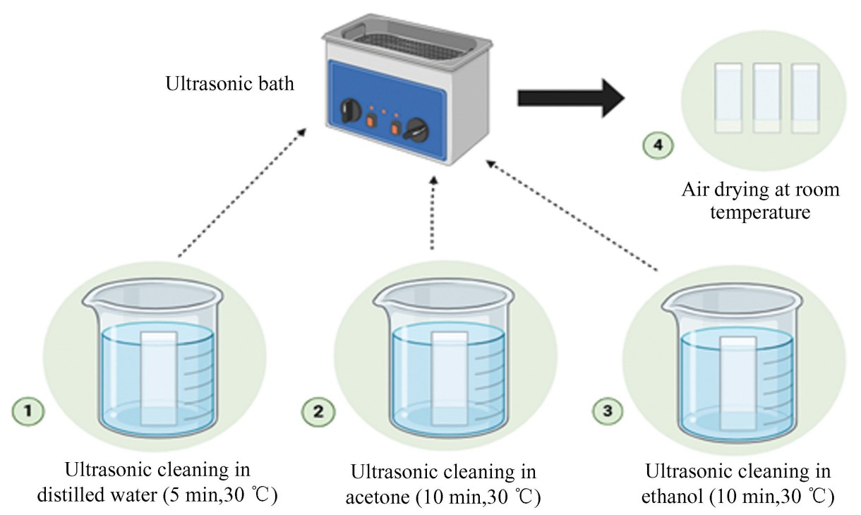
Fig.
1
Steps of the pretreatment process for conductive ITO substrates
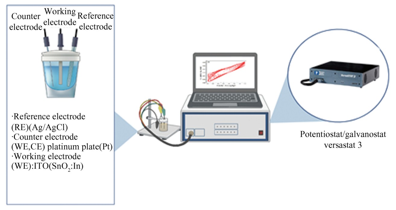
Fig.
2
Experimental setup using the VersaSTAT 3 potentiostat/galvanostat
1.4 Synthesis of ITO/PANI Thin Films
PANI thin films were electrochemically synthesized onto ITO-coated glass substrates at room temperature using two techniques: Cyclic Voltammetry(CV) and chronoamperometry(CA). The electrochemical cell consisted of a three-electrode system: ITO as the working electrode, Ag/AgCl as the reference electrode, and platinum as the counter electrode.
The electropolymerization was performed in an aqueous solution of aniline and sulfuric acid. After deposition, the resulting thin films were rinsed thoroughly with distilled water and dried in air for 12 h at room temperature. The experimental setup is illustrated in Fig. 3.
1.5 Synthesis of ITO/PANI-CuO Nanocomposite Thin Films
After electropolymerization of PANI onto ITO substrates, CuO nanoparticles(particle size<50 nm) were incorporated into the PANI matrix using the dropwise deposition method. The CuO suspension was prepared by dispersing 0.1 g of CuO powder in 100 mL of ethanol under sonication. Subsequently, 3-5 drops(approximately 15-20 μL per drop) of this suspension were carefully deposited onto the PANI-coated ITO substrate using a micropipette. The modified electrodes were then dried at room temperature under ambient conditions before characterization. This technique ensured a uniform distribution of CuO on the ITO/PANI surface, enhancing the interaction between the nanoparticles and the conductive polymer structure(as shown in Fig. 4).
1.6 Capacitance Calculation Method
The capacitance(𝐶) of the electrodes was determined from the CV curves using the following relation:
(1)
where 𝐼(𝑉) is the current(A), 𝑣 is the scan rate(V/s), Δ𝑉 is the potential window(V), and 𝐴 is the geometric electrode area(cm2). The integration was carried out over a full CV cycle to estimate the effective charge storage. In this study, the calculations were performed at a scan rate of 10 mV/s within-0.2 to+0.8 V, with an electrode area of 1 cm2.
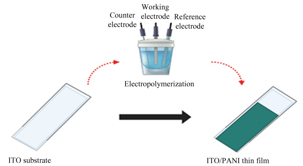
Fig.
3
Schematic representation of the electrochemical synthesis process of ITO/PANI thin films
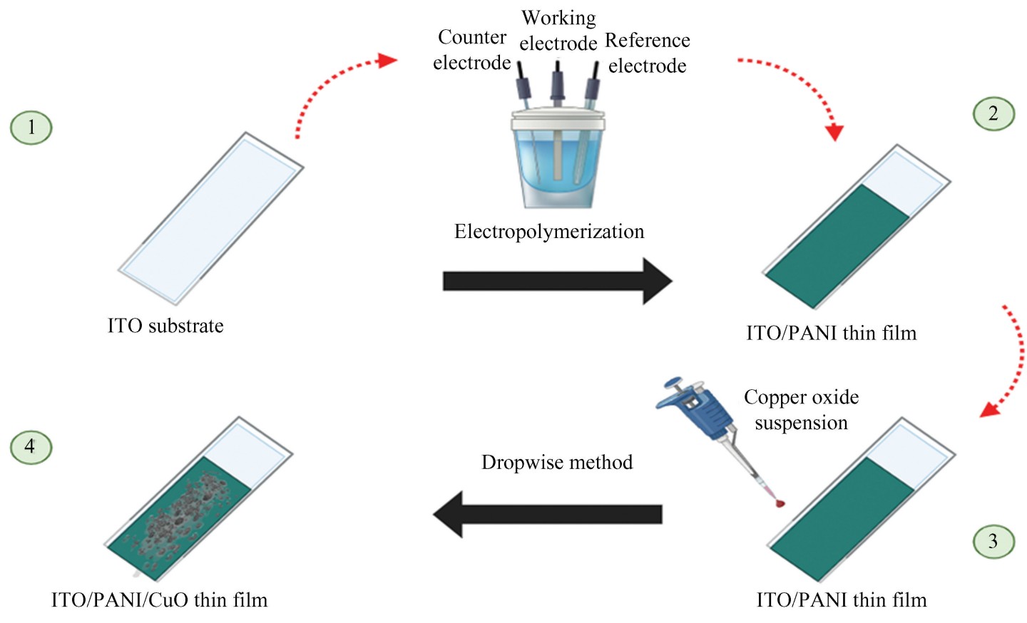
Fig.
4
Schematic representation of the fabrication process of ITO/PANI-CuO nanocomposite thin films
Note: These experiments were repeated several times on various substrates, with variations in applied potentials and scan rates, to optimize the synthesis conditions and enhance the quality of the resulting thin films.
1.7 Characterization Methods
The synthesized samples were characterized using various electrochemical techniques, including CV, CA, and Electrochemical Impedance Spectroscopy(EIS), to investigate their capacitive and conductive properties. Additionally, surface morphology and optical properties were analyzed using Scanning Electron Microscopy(SEM) and UV-visible absorption spectroscopy.
2 Results and Discussion
2.1 Electrodeposition of ITO/PANI Thin Films
Figs. 5(a) and 5(b) show the results of the electrochemical synthesis of PANI on a conductive ITO substrate using CV in a 0.5 mol/L H2SO4 solution containing aniline. The potential was scanned between-0.2 V and+1.2 V vs. Ag/AgCl at a scan rate of 50 mV/s. The successive voltammograms in Fig.5(a), recorded over 15 cycles, show a progressive increase in current density, indicating a continuous and controlled growth of the PANI thin film on the electrode surface.
In the first cycle, a pronounced anodic peak appears at around+1.1 V, corresponding to the oxidation of the aniline monomer on the bare electrode. This peak disappears in subsequent cycles, indicating the onset of electropolymerization and thin film formation. From the second cycle onward, multiple redox couples appear, characteristic of the oxidation transitions of polyaniline. The oxidation peak at+0.3 V corresponds to the transition from leucoemeraldine to the radical cation form(emeraldine)[40]. Another peak at+0.5 V may be attributed to intermediate species or byproducts, while a higher peak at+0.9 V reflects further oxidation of aniline on the PANI-modified surface.
Fig. 5(b) highlights the evolution of selected cycles(1st,2nd,5th,7th, and final), showing a progressive increase in current density and clearer redox peaks, indicating thin film thickening and improved electrochemical properties. The growing symmetry and peak stabilization suggest reversible redox behavior and homogeneous thin film morphology. At the end of the synthesis, a dark green PANI thin film—typical of the emeraldine salt form—is visually observed on the ITO substrate.
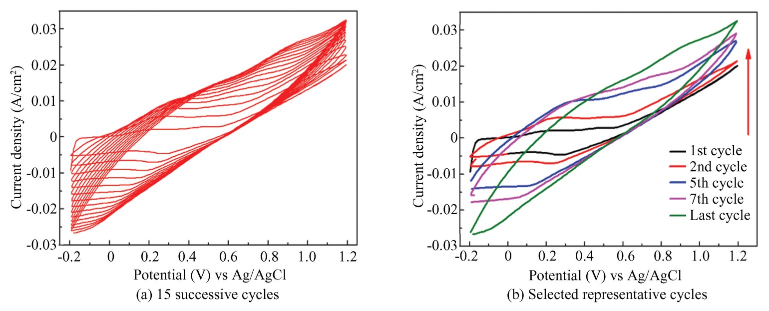
Fig.
5
Cyclic voltammograms of PANI electropolymerized on ITO
Fig. 6 presents the chronoamperogram recorded during PANI thin film deposition on ITO at a constant potential of +1.0 V vs. Ag/AgCl for 300 s. The curve displays an initial capacitive current peak due to the double-layer charging at the electrode/electrolyte interface, followed by two distinct stages:
Zone I: Instantaneous nucleation of the PANI thin film, marking the onset of deposition.
Zone II: Continuous and progressive growth by accumulation of oxidized aniline species at the electrode surface.
Eventually, the current density stabilizes into a plateau, indicating a steady-state deposition regime and well-controlled thin film growth. This behavior is typical of homogeneous electrochemical deposition and agrees with previous studies by Aynaou et al.[40] and Aguirre[41].
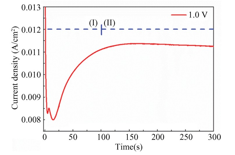
Fig.
6
Chronoamperogram recorded during the electropolymerization of PANI on ITO at +1.0 V vs. Ag/AgCl for 300 s
2.2 Morphological Studies
Scanning Electron Microscopy(SEM) was employed to examine the surface morphology of three thin film samples deposited on ITO substrates: pure PANI, pure CuO, and the PANI-CuO thin film nanocomposite, as shown in Fig. 7.
The SEM image of the PANI thin film(Fig. 7(a)) reveals a typical network of entangled nanofibers forming a porous three-dimensional architecture. This fibrillar structure, characteristic of PANI thin films electrochemically deposited in acidic media, provides a high specific surface area, which is beneficial for ion exchange and electrochemical reactions. The uniformity of the fibrous network indicates a homogeneous and well-controlled polymer growth on the ITO substrate.
In the case of the pure CuO thin film(Fig. 7(b)), the micrograph shows a distribution of well-defined crystals with cubic or quasi-cubic morphology, exhibiting minimal agglomeration. These particles have sharp edges and exhibit pronounced crystallinity, characterized by flat and regular facets. This denser and less porous structure contrasts with the fibrillar morphology of the PANI thin film.
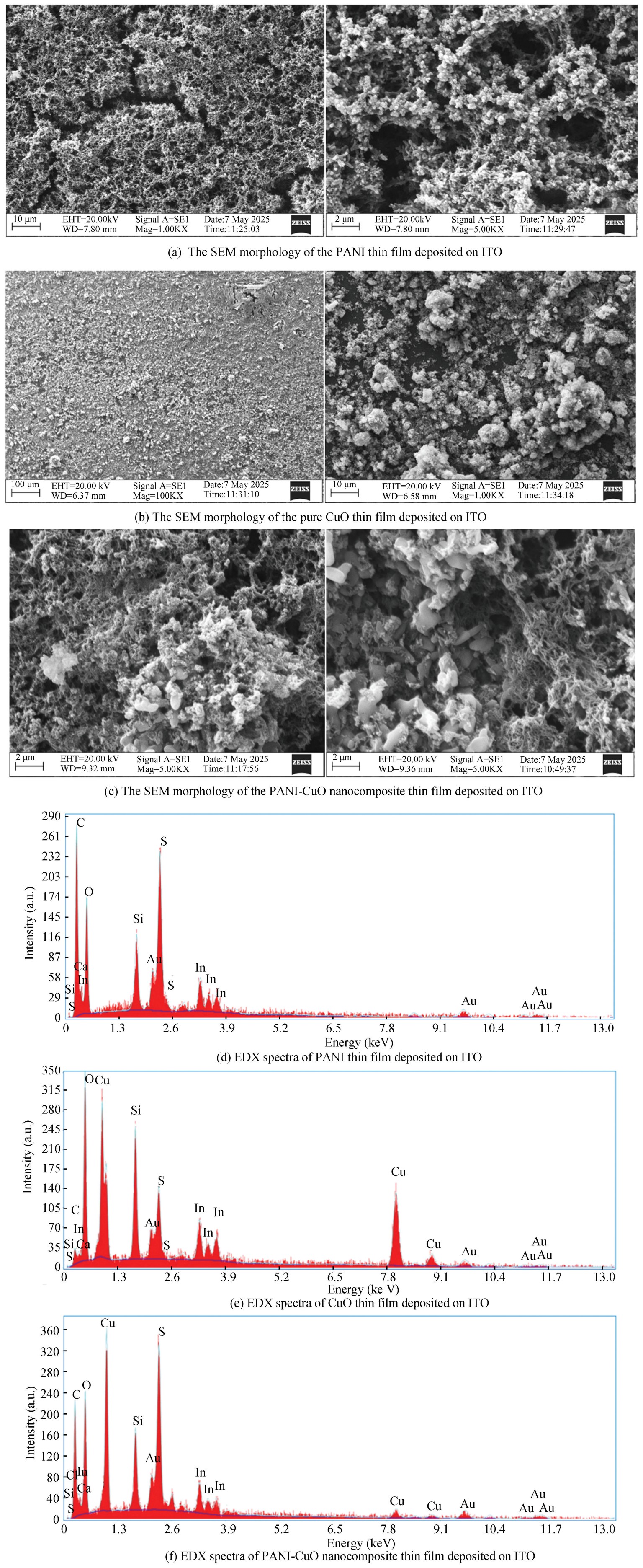
Fig.
7
SEM morphology and EDX spectra of PANI, CuO, and PANI-CuO nanocomposite thin films deposited on ITO
For the PANI-CuO nanocomposite thin film(Fig. 7(c)), the morphology appears to be a hybrid of the two previous structures. The nanofibrous network of PANI is partially decorated or embedded with dispersed CuO nanoparticles, which are visible as bright, granular features within the fibrous matrix. This combination suggests a successful incorporation of CuO into the PANI structure, potentially enhancing the material's surface area and electrochemical activity[42].
Finally, the EDX spectra Figs.7(d)-(f) corresponding to each thin film confirm the elemental composition of the samples, supporting the presence and distribution of the expected chemical species in the PANI, CuO, and PANI-CuO layers.
2.3 UV-Vis Studies
The UV-Vis spectra of PANI thin films deposited on ITO substrates, with and without the incorporation of CuO nanoparticles, are shown in Fig.8. The ITO/PANI thin film exhibits three characteristic absorption bands around 320, 430, and 800 nm. The band near 320 nm corresponds to the π-π* transition within the benzenoid rings, typical of the leucoemeraldine form of polyaniline[43-44].
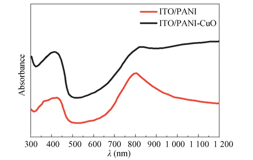
Fig.
8
UV-Vis absorption spectra of PANI and PANI-CuO nanocomposite thin films deposited on ITO substrates
The second peak, located around 430 nm, is attributed to 𝑛-π* transitions or polaronic states associated with the partially oxidized emeraldine form of the polymer[45]. Lastly, the broad band centered near 800 nm is characteristic of interband transitions between bipolaronic states, which indicates a high level of doping and good electrical conductivity.
In the case of the ITO/PANI-CuO nanocomposite, a significant increase in overall absorption intensity is observed, along with a slight red shift toward longer wavelengths. This behavior is attributed to the interaction between the conductive PANI matrix and the CuO nanoparticles, which enhances charge delocalization and strengthens electronic transitions. The presence of CuO also appears to improve the structural organization of the thin film, thereby enhancing its optoelectronic properties. These findings are consistent with those reported in Refs.[25,46-48], highlighting the potential of PANI-metal/metal oxide nanocomposites for optoelectronic and photovoltaic applications.
2.4 Electrochemical Studies of ITO/PANI and ITO/PANI-CuO Thin Films
2.4.1 Cyclic voltammetry analysis
The scan rate plays a crucial role in the electrochemical growth of PANI thin films on ITO substrates. A gradual increase in the scan rate from 5 to 100 mV/s(tested values: 5, 10, 20, 30, 50, 70, and 100 mV/s) leads to a significant acceleration of the electropolymerization process and, consequently, a faster growth of the PANI thin film. Higher scan rates result in an increased generation rate of oxidized species at the electrode surface, promoting the formation of thicker and denser thin films within a shorter time.
The voltammograms recorded at these different scan rates, as shown in Fig.9, display well-defined oxidation and reduction peaks, which are characteristic of the redox transitions between different oxidation states of PANI. The increasing peak currents with higher scan rates indicate enhanced electrochemical activity, while the shift of oxidation peaks to more positive potentials and reduction peaks to more negative values suggests a quasi-reversible behavior typical of conducting polymers.
These results confirm that precise control over the scan rate allows tuning of the thin film growth kinetics and directly influences the structural and electrochemical properties of the resulting thin film. This behavior is consistent with previous studies reported in Refs. [40,49-50].
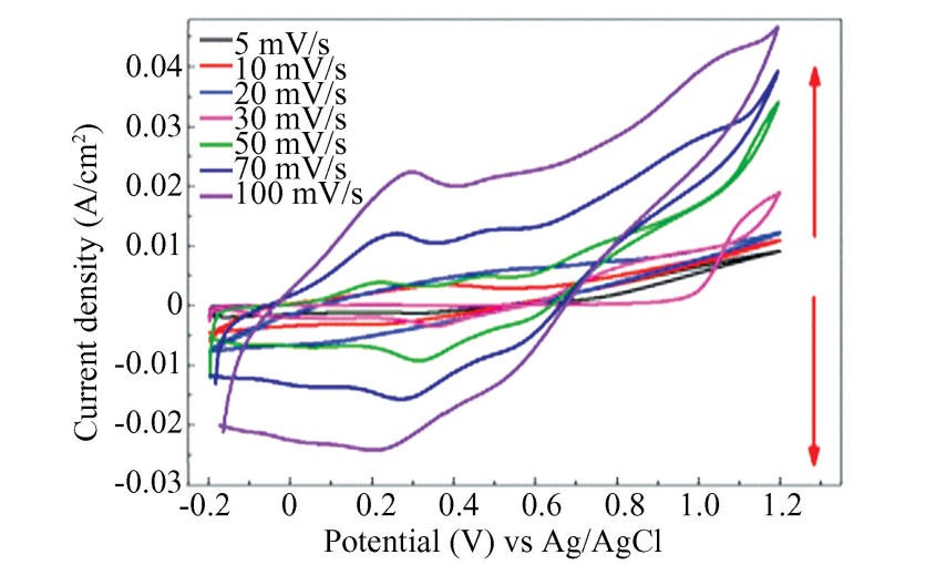
Fig.
9
Effect of scan rate on the electrochemical growth of the PANI thin film on ITO
2.4.2 Chronoamperometric analysis
Fig.10 presents the chronoamperograms recorded during the electropolymerization of the PANI thin film at four different applied potentials (0.6, 0.8, 0.9, and 1.0 V vs. Ag/AgCl). Each curve exhibits a typical two-phase behavior: an initial rapid decay in current (Zone I), followed by a gradual increase (Zone II). This evolution reflects two successive stages: the initial nucleation of the thin film, followed by continuous growth of the conductive polymer on the ITO electrode surface.
The initial current drop is attributed to the rapid formation of active nuclei, while the subsequent current rise corresponds to the thickening of the thin film and the sustained diffusion of reactive species toward the electrode surface. The current density increases significantly with the applied potential, reaching a maximum at 1.0 V(black curve). This trend indicates faster polymerization kinetics promoted by a stronger electric field, which enhances both ionic transport and the oxidation rate of the monomers.
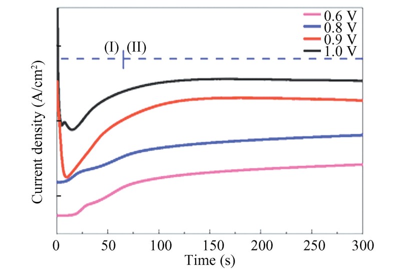
Fig.
10
Chronoamperograms recorded during the electropolymerization of the PANI thin film on ITO substrates at different potentials (0.6 V to 1.0 V vs. Ag/AgCl) over 300 s
Conversely, at 0.6 V(pink curve), the current remains low and increases slowly, suggesting slower nucleation and less dense deposition. This moderate potential leads to the formation of a more uniform and smoother thin film, although thinner.These results demonstrate that the electrodeposition potential plays a crucial role in determining the morphology and thickness of the thin film: higher potentials favor thicker, but potentially rougher, deposits, whereas lower potentials result in thinner, but more homogeneous, layers. Therefore, optimizing the applied potential is essential to tailor the thin film'sproperties for specific applications.
2.4.3 Electrochromic behavior analysis
The electrochemical and electrochromic behavior of PANI thin films deposited on ITO conductive glass substrates was investigated in an acidic medium, using a 1 mol/L sulfuric acid(H2SO4) solution as the electrolyte. The experimental results are presented in Fig.11, which shows a cyclic voltammogram recorded at a scan rate of 50 mV/s. This voltammogram reveals characteristic redox transitions of PANI, accompanied by distinct color changes, indicative of its electrochromic behavior.
Within the potential range from approximately-0.6 V to 0.1 V(vs. Ag/AgCl), the PANI thin film is in its fully reduced state, corresponding to the Leucoemeraldine Base(LB) form. This state is electrically insulating and visually appears as a pale yellow color. As the applied potential increases, a well-defined oxidation peak appears around+0.4 V, corresponding to the transition from leucoemeraldine to Emeraldine Salt(ES), the electrically conductive form. This transition is associated with a visible green coloration of the thin film and involves an anionic doping process, during which sulfate ions() are incorporated into the polymer matrix upon oxidation. This mechanism can be represented by the following reaction:
(2)
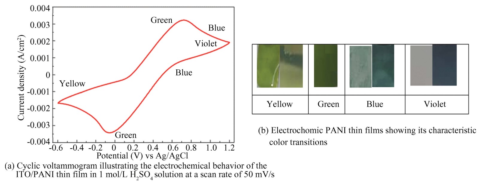
Fig.
11
Electrochemical behavior of the ITO/PANI thin films
During the reverse scan(reduction), a corresponding reduction peak is observed, indicating the release of dopant anions and the progressive return of the thin film to its initial state. This reversible doping/dedoping process confirms the electrochemical functionality of the material and the stability of its structure. The emeraldine salt form, a semi-oxidized state, is widely considered the most stable and functional phase for electrochemical and optoelectronic applications.
At higher potentials, typically beyond+0.8 V, an additional redox transition can be observed, though it appears less prominently in the experimental data. This transition corresponds to the oxidation of PANI into its pernigraniline(PN) form, which is highly oxidized and typically exhibits a dark blue or violet coloration. However, this form is known to be unstable and difficult to sustain under normal conditions.
All of these observed redox transitions are consistent with findings reported in Refs. [49-50], confirming the electrochromic nature of PANI. This behavior enables the modulation of thin film color as a function of the applied potential, making this material particularly promising for applications in electrochromic devices, optical sensors, and visual memory systems.
2.4.4 EIS analysis
EIS was employed to characterize the electrochemical properties and charge transfer resistance of the modified electrodes: ITO/PANI, ITO/CuO, and ITO/PANI-CuO. The measurements were performed over a frequency range from 104 Hz to 0.01 Hz, using a signal amplitude of 100 μA(RMS) distributed over 30 points. The results are presented as Nyquist plots in Figs.12(a)-(c), where Zre and Zim represent the real and imaginary components of the impedance, respectively.
The Nyquist curves typically exhibit two distinct regions: a semicircular arc at high frequencies, corresponding to the charge transfer resistance(𝑅ct), and a sloped straight line at low frequencies, related to diffusion processes within the electrode or the electrolyte[51-52].
For the ITO/PANI electrode(Fig.12(a)), the diagram reveals a very large semicircular arc, with a charge transfer resistance reaching approximately 3 000 Ω·cm2. This high 𝑅ct value suggests poor electronic conductivity, likely due to imperfect molecular organization or low doping density in the polyaniline thin film[53].
In contrast, the ITO/CuO electrode(Fig.12(b)) shows a more moderate arc, indicating a significant reduction in charge transfer resistance to about 1 000 Ω·cm2. This improvement can be attributed to the p-type semiconducting nature of CuO, which partially facilitates charge transfer through its majority charge carriers(holes). However, the resistance remains relatively high, reflecting an imperfect electrode/electrolyte interface.
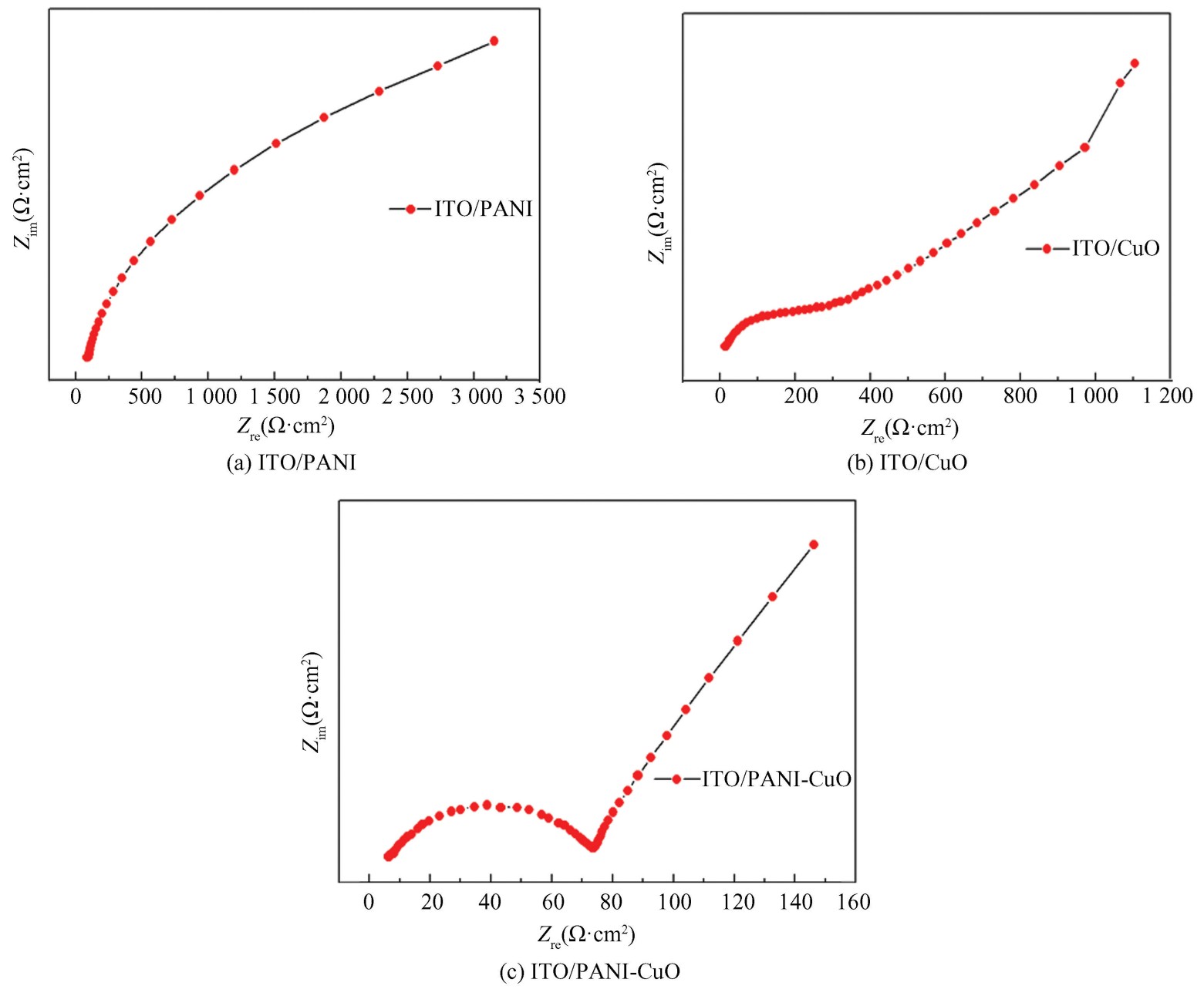
Fig.
12
Nyquist plots obtained by EIS for the modified electrodes over a frequency range from 104 Hz to 0.01 Hz with a 100 μA RMS amplitude
The hybrid ITO/PANI-CuO electrode(Fig.12(c)) demonstrates significantly improved electrochemical behavior. The diagram features a much smaller semicircular arc followed by a well-defined inclined line. The charge transfer resistance is considerably reduced(~80 Ω·cm2), indicating favorable charge kinetics at the interface. This result demonstrates the synergistic effect between PANI and CuO: PANI provides a highly dopable conductive matrix, while the CuO nanoparticles increase the active surface area and enhance both ionic and electronic transport. This synergy leads to a more homogeneous and reactive interface, thereby facilitating charge transfer across the electrode[47,54-55]. Quantitatively, fitting the high-frequency semicircle yields 𝑅ct values of~3 000 Ω·cm2 for ITO/PANI,~1 000 Ω·cm2 for ITO/CuO, and~80 Ω·cm2 for the ITO/PANI-CuO composite. The~38× decrease from PANI to PANI-CuO evidences significantly facilitated interfacial charge transfer owing to the synergistic coupling between the dopable PANI matrix and the CuO nanophase.
2.5 Evaluation of the Supercapacitive Properties of ITO/PANI and ITO/PANI-CuO Thin Films
To assess the performance of the modified electrodes developed in this study, their capacitive behavior as supercapacitors was investigated using cyclic voltammetry within a potential window ranging from-0.2 to 0.8 V vs. Ag/AgCl at a fixed scan rate of 10 mV/s.The results presented in Fig.13 reveal clear differences among the three tested configurations.
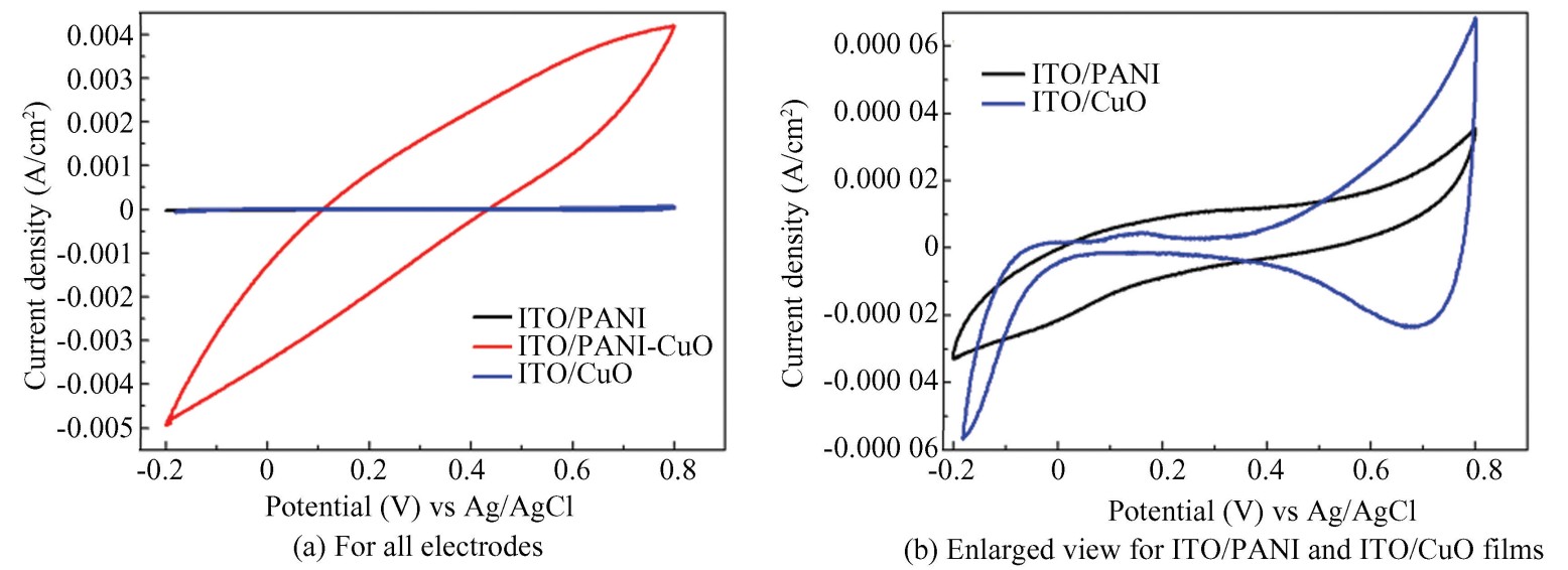
Fig.
13
Study of the capacitive behavior of ITO/PANI, ITO/CuO, and ITO/PANI-CuO electrodes
The ITO/PANI-CuO nanocomposite electrode exhibits the highest current density and the largest enclosed CV curve, directly reflecting its superior charge storage capacity. In contrast, the ITO/PANI electrode shows a quasi-rectangular and symmetrical profile, indicative of good capacitive reversibility, while the ITO/CuO electrode presents a nearly linear response with low current density, highlighting its limited pseudocapacitive contribution. This comparison confirms that the incorporation of CuO into the PANI matrix markedly improves the electrochemical performance, as evidenced by the enhanced specific capacitance arising from the synergy between the intrinsic conductivity of PANI and the pseudocapacitive properties of CuO[56-57].
The remarkable enhancement observed in the ITO/PANI-CuO electrode can be attributed to several synergistic effects. CuO nanoparticles provide abundant redox-active sites, while their nanoscale dispersion promotes electrolyte penetration and ionic transport. Meanwhile, the PANI framework ensures continuous electronic pathways, structural stability, and rapid charge transfer. Similar synergistic behavior has been reported in other conductive polymer/metal oxide systems; for example, CuO-CuO-polypyrrole composites showed improved capacitance and reduced charge-transfer resistance, while ternary CuO@Cu4O3/rGO/PANI structures achieved high capacitance and excellent rate capability due to enhanced redox kinetics and efficient electron conduction networks[58-59]. Collectively, these findings align with recent reviews that emphasize the critical interplay between porosity, conductivity, and redox activity in hybrid metal oxide-PANI systems for achieving superior supercapacitor performance[60]. Beyond qualitative observations, the CV data were further analyzed to extract capacitance values. Using the integration method described in the Methods section, the areal capacitances were calculated to be~0.548 F/cm2 for ITO/PANI-CuO, compared with~0.004 27 F/cm2 for ITO/PANI and~0.003 18 F/cm2 for ITO/CuO. This represents an enhancement of more than two orders of magnitude relative to pristine PANI, fully supporting the synergistic effect of CuO incorporation. Importantly, these values fall within the range reported for PANI/metal oxide hybrid thin films(0.1-1.0 F/cm2), thereby confirming both the reliability of the present results and the progressive advantage of the ITO/PANI-CuO electrode. This improvement is also consistent with the reduced 𝑅ct observed in EIS analysis, underscoring the superior pseudocapacitive kinetics and stability of the nanocomposite structure.
A comparative analysis with recently reported PANI-based composites is provided in Table 1. This comparison highlights the strong competitiveness of our PANI/CuO thin films in terms of capacitance and charge-transfer resistance.
Table
1
Comparative capacitance performance of PANI/CuO thin films and recently reported PANI-based composites

Note:“*” indicates that the unit is F/g;“**” indicates that the unit is mF/cm2; “***” indicates that the unit is F/cm2; Capacitance values are reported in gravimetric(F/g) or areal(F/cm2 or mF/cm2) units according to the respective reference.
3 Conclusions
In summary, this work successfully demonstrated the electrochemical synthesis of nanostructured thin films of PANI, CuO, and their PANI/CuO nanocomposites on conductive ITO substrates. This strategy provided precise control over film growth while ensuring homogeneous incorporation of CuO nanoparticles into the PANI matrix, leading to well-organized nanocomposite structures. SEM analysis revealed a uniform nanofibrillar architecture with well-dispersed CuO nanoparticles, highlighting the strong synergy between the two components. This structural reinforcement was accompanied by a significant enhancement in electrical conductivity and electrochemical stability. Cyclic voltammetry confirmed superior capacitive behavior of the nanocomposite compared with pristine PANI and CuO thin films, with a clear expansion of the voltammetric area indicative of higher charge storage. Quantitative electrochemical analyses further demonstrated that the ITO/PANI-CuO electrode achieved a charge-transfer resistance of~80 Ω·cm2(compared with~3 000 Ω·cm2 for ITO/PANI and~1 000 Ω·cm2 for ITO/CuO) and an areal capacitance of~0.548 F/cm2, representing an enhancement of more than two orders of magnitude relative to pristine PANI(~0.004 27 F/cm2). These outstanding improvements arise from the synergistic interplay between the conductive PANI network and the redox-active CuO nanoparticles, which together facilitate efficient ion diffusion, rapid electron transport, and accelerated interfacial charge transfer. Overall, the findings establish the PANI/CuO nanocomposite as a cost-effective, scalable, and durable electrode material for next-generation supercapacitors. Future studies may focus on optimizing synthesis parameters and exploring ternary or hybrid systems to further boost electrochemical performance.
