Abstract
In the design of air foil bearings, nominal radial clearance is an important parameter that affects bearing performance. To analyze radial clearance influence on bearing lubrication and dynamic performance, a mechanical model that simplifies the foil structure as a two-dimensional thin plate finite element model with an elastic support is established using the theory of elasticity. The calculation model comprehensively considers the interactive forces of bumps and the frictions between the top foil and bump foil, as well as between the bump foil and bearing bushing. A flow-solid coupling calculation model is established based on the compressible gas Reynolds equation. By using perturbation methods, the calculation model for bearing dynamic performance is established. The reliability of the model is verified through experiments measuring the friction torque of the bearing. Through a specific case study, the influences of radial clearance and rotational speed on lubrication and dynamic performance are calculated. In addition, the influence of the foil's structural parameters on bearing performances is also studied.
0 Introduction
Currently, air foil bearings are critical for extreme-condition rotating systems[1-2]. Among various air foil bearings, bump-type air foil bearings are the most successful and widely implemented design[3]. The radial clearance of bump air foil journal bearings is one of the crucial parameters affecting their lubrication and dynamic performance, but relevant studies are not yet sufficient. Consequently, it is necessary to comprehensively study the influence of radial clearance on the performance of the bump air foil journal bearing.
Walowit et al.[4] conducted theoretical analysis on bump foil journal bearings, and established an elastic deformation model of foil structure for the first time to determine its elastic coefficients. Heshmat et al.[5-6] simplified the bump foil as a linear spring and developed an analytical solution for gas film thickness considering foil deformation. The bearing capacity of the foil bearings was assessed. Radil et al.[7] examined the influence of radial clearance on bearing load capacity. The bearing had an optimal radial clearance introducing a maximum load capacity coefficient when frictional heat was considered. To obtain an optimal foil structure, many studies about the influence of structural parameters on bearing performance have been conducted, including length-to-diameter ratio, foil flexibility and thickness, and the size parameters of the bump arch. These studies investigated how these parameters affect the vibration of the supported rotor and the performance of the bearing[8-12]. Mahner et al.[13-15] proposed a fully coupled thermoelastic gas dynamic pressure model. The effects of mechanical preload on the thermodynamics, startup friction torque, and other performances of three-lobed foil gas bearings were investigated through computational and experimental analyses. Kim[16] conducted a comparative analysis of load capacity, stiffness distribution, and bearing stability with single and three-lobed foil structures. It showed that foil bearings with a single lobe have a greater load capacity but have lower onset speeds of instability. Shi et al.[17-19] analyzed how rotational speed, nominal clearance, bump foil geometry, and loading direction affect the two types of bearings. It was discovered that the load capacity of bearings was significantly influenced by nominal clearance, and load capacity decreases with increasing nominal clearance. Guan and Feng[20] coupled an elastic mechanical model with compressible gas Reynolds equation to predict bearings' static and dynamic performances, and found that the dynamic main stiffness and damping coefficients increase with decreasing nominal clearance. Sim et al.[21] and Walter et al.[22] found that the minimum clearances affect the dynamic performances and stability of bearings. Xiong et al.[23] analyzed effects of different foils' friction coefficients on the dynamic performance based on CFD methods, and revealed that dynamic stiffness and damping coefficients are underestimated when friction coefficient exceeds 0.3. Cheng et al.[24] proposed a method for identifying dynamic coefficients of bearings. The frequency response function and equivalent coefficient methods were used to identify the dynamic coefficients.
Load capacity, stability, and vibration damping of air foil bearings depend critically on the bump foil[25]. Arghir and Benchekroun [26] proposed a contact mechanics model based on a structural model of bump foil bearings, which considered gaps and close/loose contacts in the foils and was more accurate in simulating manufacturing errors in the foils. A novel fully-coupled elastic-fluid model capturing foil contact/separation/friction dynamics was developed by Gu et al.[27]. By employing a double-layered foil, adjusting the layout of the foils and increasing the thickness of the foils, Xu et al.[28-29] increased the bearing's structural stiffness and experimentally verified that double-layered foils could enhance the bearing damping. By adding four layers of foil to the bearing, Li et al.[30]examined the mechanical relationship of contact between each layer of foil. Zhao et al.[25] analyzed the Coulomb damping dissipation performance based on a two-dimensional mechanical model. Liang et al.[31] used 3D FEM to analyze the influences of structural parameters of bump foil on bearing load capacity. The results showed that the bump arch width was an important parameter affecting the load capacity of bearings, while the bump arch height minimally affected the bump foil stiffness.
It can be seen that radial clearance is a crucial geometric parameter that affects the performances of air foil bearings. However, its influence on bearing dynamic performance was rarely investigated according to the literature analysis. Therefore, a mechanical model simplifying the foil structure of the bearing as a two-dimensional thin plate finite element model with an elastic support was established using the theory of elasticity in Section 1. Friction behaviors between bump foil-top foil and bump foil-bearing bushing interfaces were incorporated. Then, the mechanical model of bearing is coupled with the compressible gas Reynolds equation. Subsequently, the reliability of the proposed model is verified by experiments in Section 2.1. This study numerically investigates how radial clearance and foil structural parameters affect bearing lubrication and dynamic performance.
1 Mechanical Modelling
1.1 Establishment of Lubrication Mechanical Model
Fig. 1 shows the position relationship between the bump air foil bearing and rotor before and during operation, where 𝑂𝑏 and 𝑂𝑟 are the bearing's center and rotor's center, respectively. When the bearing is operating, elastic deformation of bumps is caused by the air film pressure shown in Fig. 2(a). Contrary to Ref.[11], the mechanical model of bump foil bearing developed more comprehensively considers friction forces, stiffness of foils, damping of foils and interactive forces between bumps, which can more realistically reflect the performance of the bearing. The force analysis of the foils is carried out under the following assumptions:
1) The bumps are always in contact with the inner surface of the bearing bushing.
2) The bumps' displacements in the circumferential direction are from the fixed end to the free end.
3) The force is focused on the top of the bumps.
4) The deformation of the bump and top foils is within the elastic range during operation.
The force diagram of bumps is shown in Figs. 2(b)-(d). 𝑓 represents friction. 𝐹left and 𝐹right represent the interactive forces between bumps. Vertical loads 𝐹, 𝐹1 and 𝐹2 act on the top, left, and right sides of each bump, respectively. The bump foil deformation 𝑤𝑏 is calculated using Castigliano's second theorem. As shown in Fig. 2(b), the forces balance equation in horizontal and vertical directions and the moment balance equations of a bump can be obtained as follows:
(1)
where 𝑓=𝜂𝐹, 𝑓1=𝜂1𝐹1, 𝑓2=𝜂1𝐹2, 𝜂 and 𝜂1 are friction coefficients between bump foil-top foil and bump foil-bearing bushing, 𝑅0 is bump arch radius, 𝑙 is bump arch half-length, 𝜑 is bump arch half-angle. 𝐹a is the horizontal right additional force.
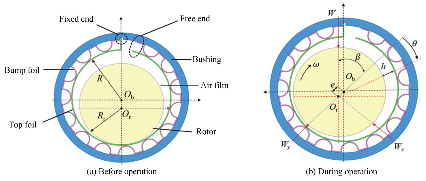
Fig.
1
Schematic diagram of the foil bearing
The bending moment of a bump is:
(2)
Applying Castigliano's second theorem and integrating over Eq.(2), the vertical and horizontal deformations of the bump can be obtained as follows:
(3)
The bump is equated to a spring with damping as shown in Fig. 2(a), and the bump arch stiffness is as follows:
(4)
(5)
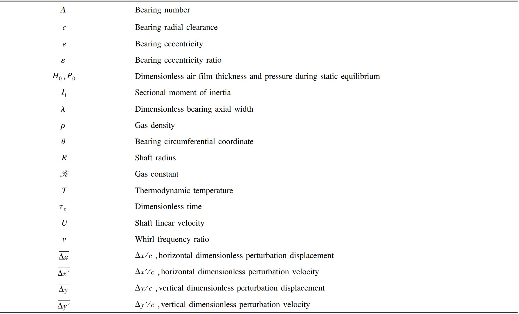
where 𝜁 is proportional damping coefficient, 𝜔𝑒 is vortex frequency. 𝐹= 0 at the non-contact position of the bump and top foils. The total stiffness and damping matrices 𝐾𝑏,𝐶𝑏 of the bump foil are obtained by integrating 𝐾𝑏 and 𝐶𝑏.
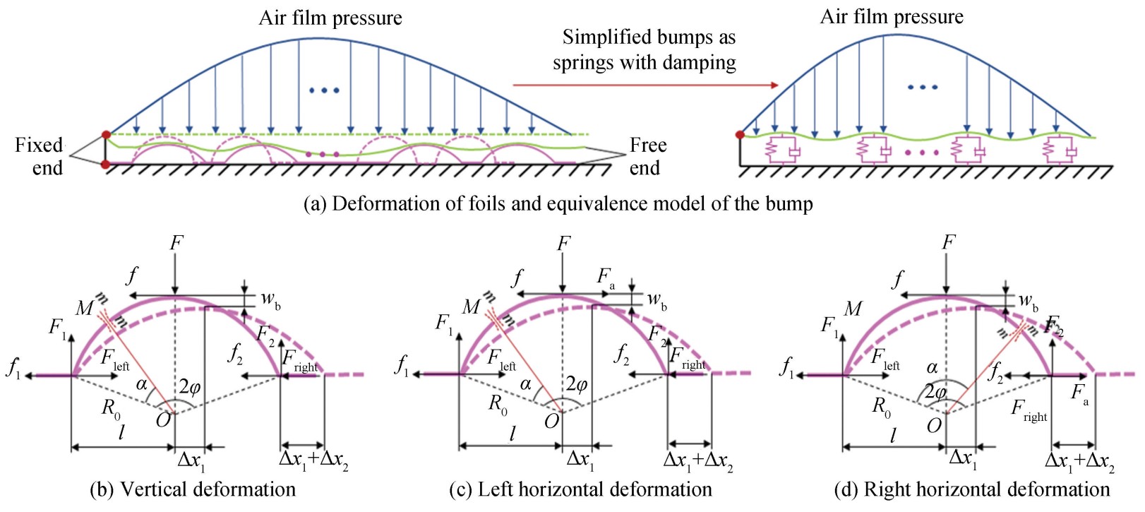
Fig.
2
Schematic of the force and deformation of the bump foil
The thin plate theory is used to establish the finite element model of the top foil(as shown in Fig. 3). The top foil deformation is smaller than the thickness 𝑡ₜ, so the small deflection theory is adopted to improve calculation accuracy.
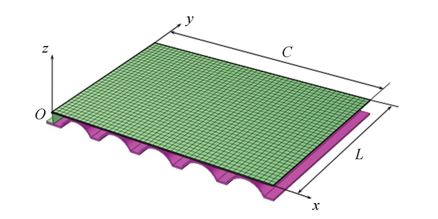
Fig.
3
Schematic of the finite element model of the top foil
As shown in Fig.4(a), the top foil is discretized using rectangular elements. The element dimensions are 𝑎, 𝑏 in 𝑥 and 𝑦 directions, respectively. A rectangular element includes four nodes(𝑖, 𝑗, 𝑚, 𝑛). The displacements and forces of the node are expressed as shown in Eq.(6):
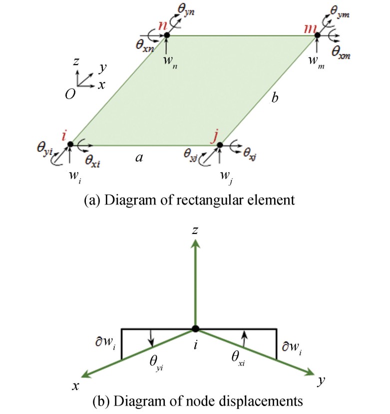
Fig.
4
Schematic diagram of a rectangular thin plate element
(6)
The displacement function during the bending of a thin plate can be expressed as follows:
(7)
Taking node 𝑖 as an example, according to the geometric relationship(as shown in Fig. 4(b)), the approximation is taken as sin𝜃𝑥𝑖=𝜃𝑥𝑖, and sin𝜃𝑦𝑖=𝜃𝑦𝑖. Then 𝜃𝑥𝑖=∂𝑤𝑖/∂𝑦𝑖, 𝜃𝑦𝑖=-∂𝑤𝑖/∂𝑥𝑖. Similarly, nodes 𝑗, 𝑚, 𝑛 are processed as above and the 12 coefficients 𝜅1,𝜅2,...,𝜅11,𝜅12 of Eq.(7) are obtained. The deflection matrix of rectangular elements is:
(8)
where 𝑁 is the shape function of rectangular elements and expressed as follows:
(9)
where 𝑁𝑖, 𝑁𝑥𝑖, 𝑁𝑦𝑖,···, 𝑁𝑛, 𝑁𝑥𝑛, 𝑁𝑦𝑛 are expressed as follows:
(10)
where 𝑔=𝑖,𝑗,𝑚,𝑛.
The stress matrix of a rectangular element is:
(11)
The stiffness matrix for rectangular elements is:
(12)
The damping matrix for rectangular elements[32] is:
(13)
𝐷e is the elastic matrix and is expressed as follows:
(14)
where 𝐸 is the elasticity modulus of foils, 𝑢𝑏 is Poisson's ratio of foils. The top foil overall stiffness 𝑲t is obtained by standard integration rules. The force matrix on the top foil is recorded as 𝑭. The relationship of 𝑲t and 𝑭 is:
(15)
where 𝒒 is the top foil overall displacement matrix. Total bearing stiffness and damping result from combined top and bump foil contributions, i.e. 𝑲f=𝑲t+𝑲b and 𝑪f=𝑪t+𝑪b.
Thus, the lubricating air film thickness is:
(16)
where 𝑐=𝑅-𝑅𝑟 is nominal radial clearance. 𝑅 is bearing radius. 𝑅𝑟 is rotor radius. 𝑒 is eccentricity distance. The dimensionless form of Eq.(16) is:
(17)
where 𝜀 is eccentricity of the bearing.
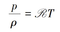
The formula for the ideal gas state is:
(18)
Neglecting pressure-dependent viscosity, the isothermal compressible Reynolds equation simplifies to:
(19)
Eq.(19) is dimensionless:
(20)
where 𝑥=𝑅𝜃, 𝐻=, 𝑧=λ, 𝑃=, 𝛬=, 𝑈=𝜔𝑅𝑟, 𝑣=, 𝜏e=𝜔e𝑡. λ is dimensionless length in axial width direction, 𝛬 is bearing number, 𝜏e is dimensionless time, 𝜔 is rotor angular velocity.
1.2 Calculation Model for Lubrication Performances
The static air film pressure of bearings is determined by the static operating point and is independent of time[34]. When the bearing is in a stable operation, the lubricating air exhibits steady flow. Thus, the compressible gas Reynolds equation is as follows:
(21)
The boundary conditions of dimensionless pressure during the solution of lubrication performances are:
(22)
As shown in Fig.1, the bearing load capacity 𝑊 consists of 𝑊𝑥 and 𝑊𝑦 during the stable operation, which can be calculated as follows:
(23a)
(23b)
(24)
The viscous friction torque of the lubricating film acting on the surface of the shaft is expressed as follows:
(25)
The friction power loss to overcome the viscous friction torque is expressed as follows:
(26)
Due to bearing symmetry in the axial direction, the side leakage flow rate of air is:
(27)
1.3 Calculation Model for Dynamic Performances
The criteria for measuring the dynamic performance of bump air foil bearings primarily involve dynamic stiffness and damping coefficients. Dynamic coefficients are calculated using perturbation methods. Air film pressure depends on rotor displacement and speed:
(28)
where 𝐹𝑁𝑥, 𝐹𝑁𝑦 are air-film horizontal and vertical forces, respectively. 𝑥 and 𝑦 represent rotor's horizontal and vertical displacement, respectively. 𝑥′ and 𝑦′ denote its velocity components.
When the rotor is operating stably, perturbation displacements Δ𝑥 and Δ𝑦, perturbation velocities Δ𝑥′ and Δ𝑦′ are applied to the rotor. The forces are in a Taylor series expansion:
(29)
where the subscript “0” represents the quantity in the equilibrium position. Δ𝑥, Δ𝑦, Δ𝑥′,Δ𝑦′→0. Neglect the term 𝑂(Δ𝑥2,Δ𝑦2,Δ𝑥′2,Δ𝑦′2), stiffness and damping coefficients are:
(30a)
(30b)
Then Eq.(29) is expressed as the matrix form:
(31)
where 𝑲, 𝑪 are stiffness and damping matrices, respectively, and expressed as:
(32)
The dimensionless air film thickness and pressure, and total radial deformation of top foil are respectively written as: . The first-order Taylor series expansion of 𝑃, 𝐻, and ignoring the higher order quantities is:
(33)
where 𝑃𝑥,𝑃𝑦,𝑃𝑥′,𝑃𝑦′ are pressure disturbances caused by Δ𝑥,Δ𝑦,Δ𝑥′,Δ𝑦′,respectively. 𝐻𝑥,𝐻𝑦,𝐻𝑥′,𝐻𝑦′ are air film thickness disturbances caused by Δ𝑥,Δ𝑦,Δ𝑥′,Δ𝑦′,respectively. ,,, are foil deflection disturbances caused by Δ𝑥,Δ𝑦,Δ𝑥′,Δ𝑦′,respectively.
Substituting Eq.(33) into Eq.(20), the perturbation pressure equations are as follows:
(34)
(35)
(36)
(37)
When the shaft is subjected to the above perturbations, 𝐻 is expressed as follows:
(38)
Combining Eq.(38) with Eq.(33) yields:
(39)
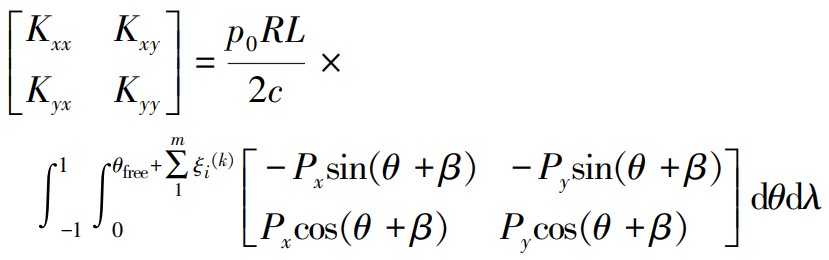
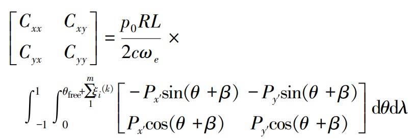
By substituting Eq.(39) into Eqs.(34)-(37), the air film pressure 𝑃𝑥, 𝑃𝑥′, 𝑃𝑦, and 𝑃𝑦′ can be obtained. Then, dynamic performance coefficients are:
(40)
(41)
The boundary conditions of dimensionless pressure during the solution of dynamic performance coefficients are as follows:
(42)
1.4 Numerical Calculation Method
In this study, the dimensionless Reynolds equation is solved using the finite difference method with iterative point-by-point convergence. As shown in Fig. 5, the load area is gridded circumferentially and axially. The area between adjacent bumps is divided into 𝜒 parts. The initial step length of each grid is equal, which can be expressed as follows:
(43)
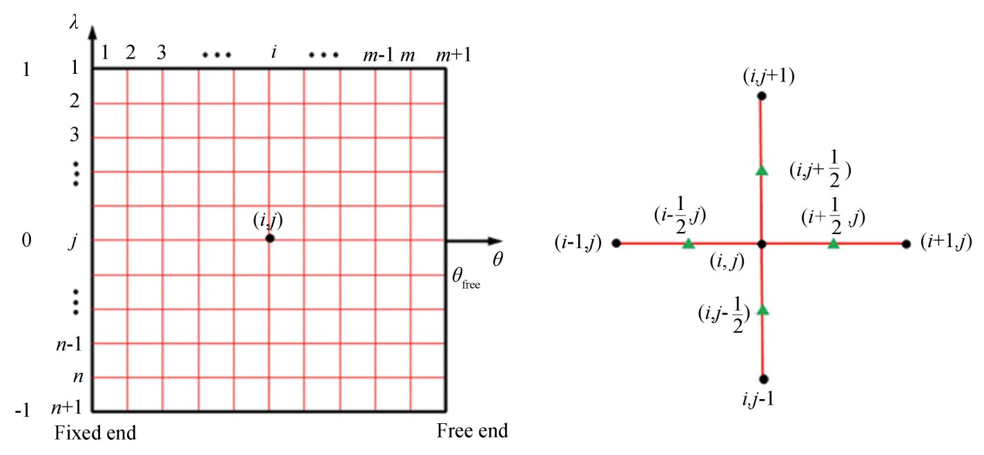
Fig.
5
Schematic of mesh and difference quotient
Starting from the second iteration, the grid step length in the circumferential direction of foils changes with deformation. Therefore, during 𝑘-th iteration, the grid step length can be expressed as follows:
(44)
where represents the change in the 𝑖-th grid in the circumferential direction during the 𝑘-th iteration.
In the axial direction, the grid step length does not change with the number of iterations. Therefore, it can be expressed as follows:
(45)
The high-precision central difference quotient is used to replace the partial derivative terms. The convergence criteria for air film pressure(𝐸𝑃) and load(𝐸𝑊) capacity are:
(46)
(47)
The convergence criteria for the calculation of the dynamic performance are:
(48)
(49)
2 Results and Discussion
2.1 Experimental Verification
As shown in Fig. 6, the friction torque of the bearing was measured on a bearing test rig developed in our laboratory. The bearing basic parameters are shown in Table 1.
The experiments were conducted at 26 ℃ whith a rotational speed of 𝑛=20 000 r/min. Friction torque 𝑇𝑟 is measured with different radial clearances 𝑐 and loads 𝑊 during stable operation.
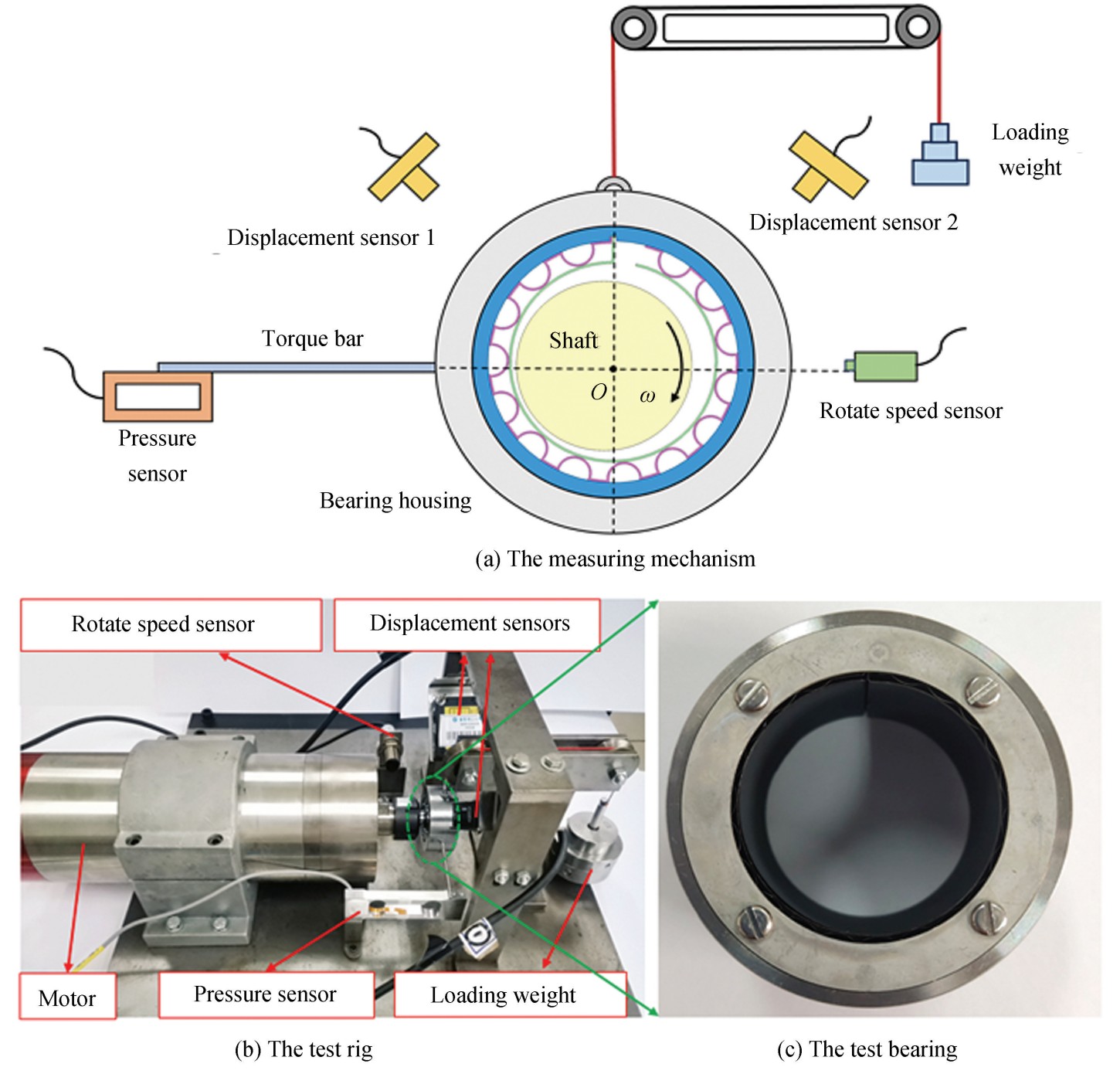
Fig.
6
Bump air foil bearing test rig
Every experimental datum represents the average of five measurements. The comparative results of experiments and numerical simulations are shown in Fig.7. It can be seen that the friction torque 𝑇𝑟 decreases gradually with radial clearance 𝑐, which varies within the range of 105-255 μm when the load 𝑊=5 N. 𝑇𝑟 increases with 𝑊, which varies within the range of 3.5-5.5 N when the radial clearance 𝑐=210 μm. Consistent experimental and numerical results demonstrate the reliability of the theoretical model.
Table
1
Basic parameters of the bearing
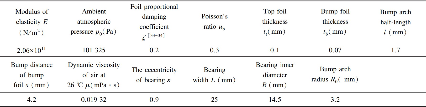
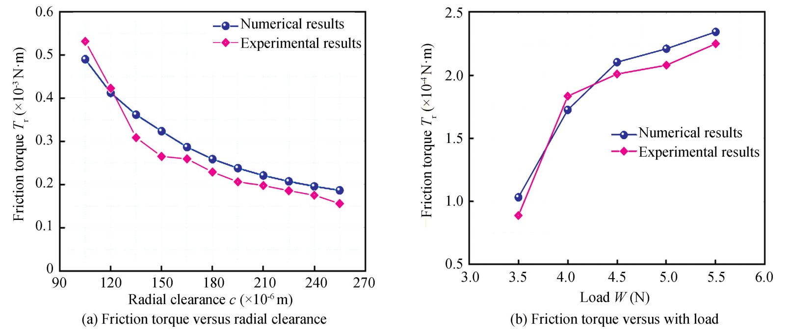
Fig.
7
Variation of friction torque with radial clearance and load
2.2 Influences of Radial Clearance on Lubrication Performances
After verifying the calculation model established in this study by experiments, the performance of the bump foil bearing was numerically studied. Based on the theoretical model established above, the dimensionless air film pressure and thickness distributions were first calculated when 𝑛=50 000 r/min, 𝑐=30 μm, and 𝑊=5 N(as shown in Fig. 8).
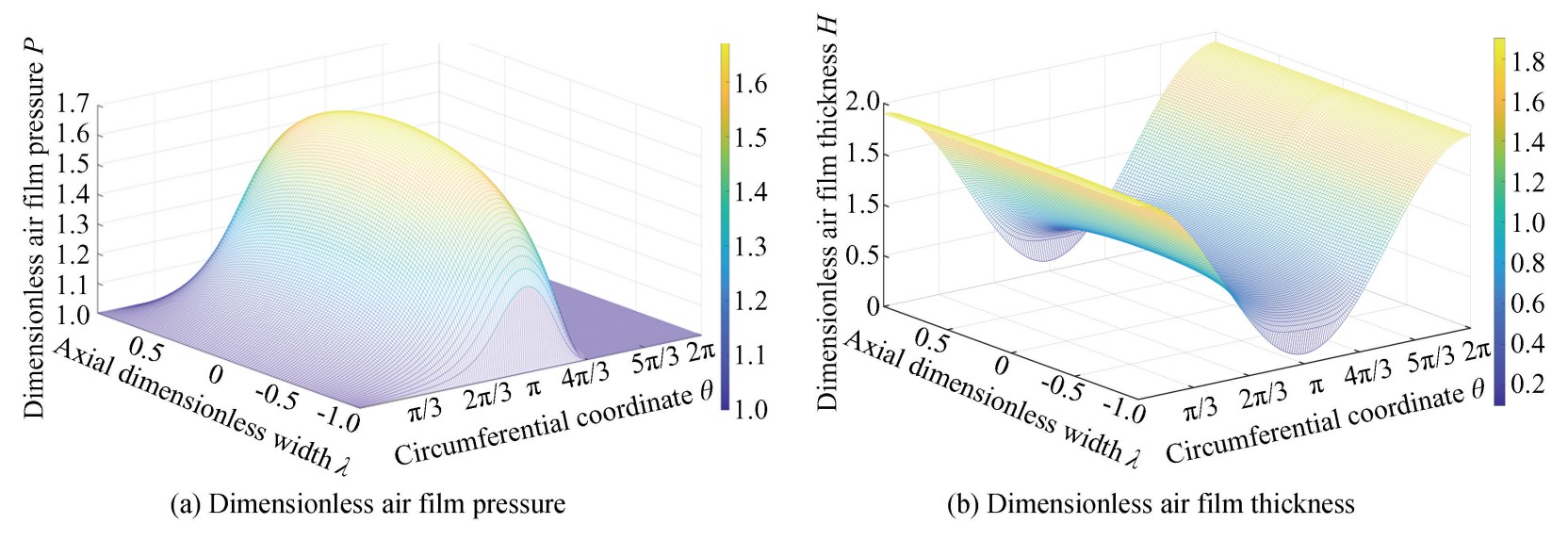
Fig.
8
Dimensionless air film pressure and thickness distribution of bump air foil bearing
The results in Fig. 9 and Fig. 10 are calculated at the middle plane(λ=0) of the bearing when load 𝑊=5 N. Fig. 9 demonstrates radial clearance effects on dimensionless air film pressure and thickness when 𝑛=50 000 r/min. Fig. 10 shows the relationship of the maximum air film pressure 𝑃max and the minimum air film thickness 𝐻min with radial clearance under different rotational speeds when 𝑊=5 N. It can be seen that 𝑃max increases with radial clearance but decreases with rotational speed, while 𝐻min decreases with radial clearance and increases with rotational speed.
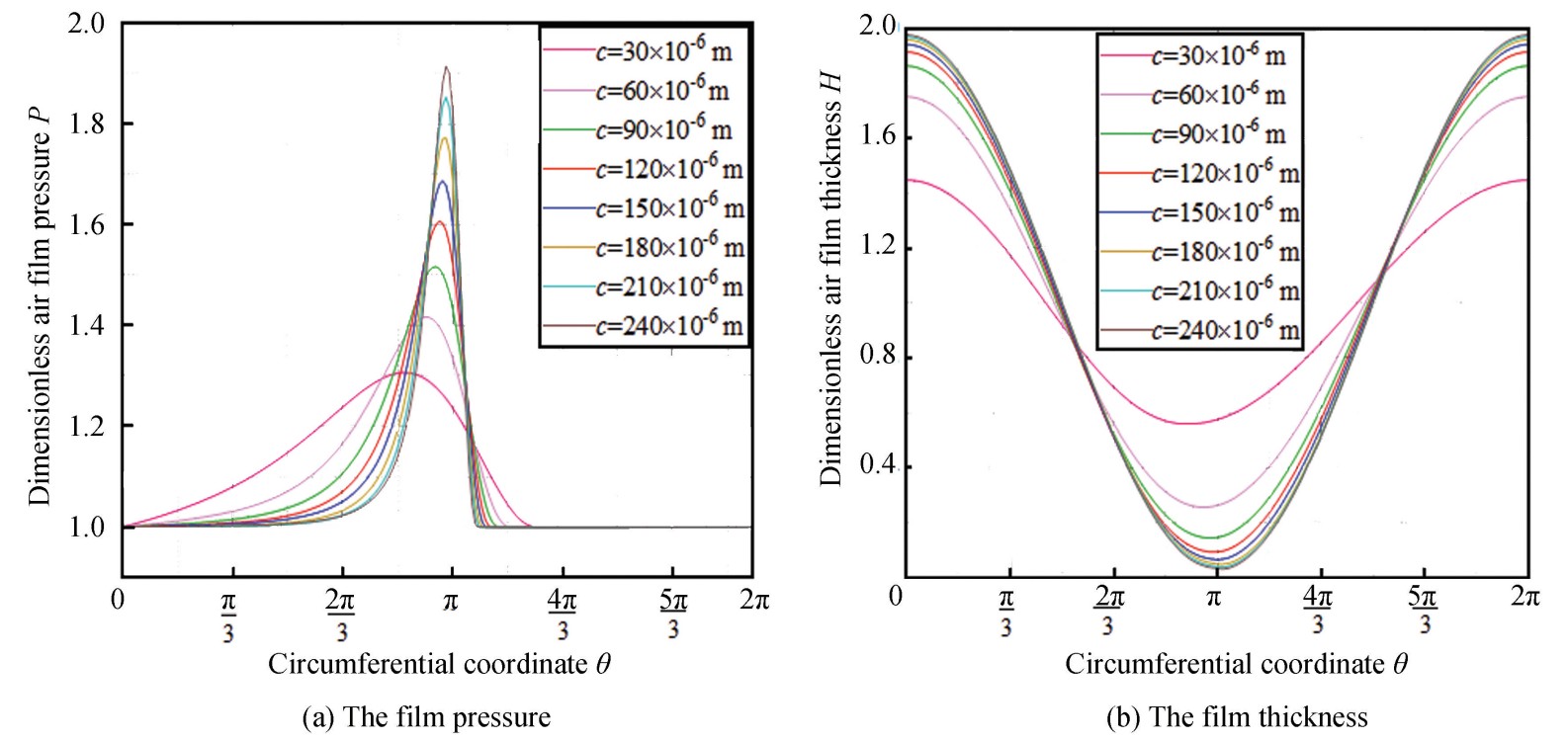
Fig.
9
Dimensionless air film pressure and thickness distribution
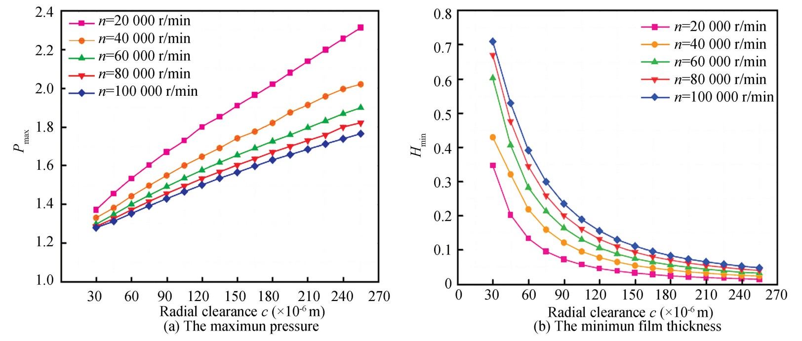
Fig.
10
Dimensionless maximum air film pressure and minimum air film thickness versus radial clearance
Localized contact between rotor and bearing inner surfaces occurs when the minimum air film thickness is less than the roughness of the two surfaces, which result in bearing failure. Therefore, the maximum load capacity refers to the capacity when the minimum air film thickness is 2 μm[35]. Fig. 11(a) shows the maximum load capacity 𝑊max versus radial clearance. It can be seen that 𝑊max decreases with radial clearance but increases with rotational speed.
Figs. 11(b)-(d) show that the friction torque 𝑇𝑟, friction power loss 𝑁 and side leakage flow rate of gas 𝑄𝑧 versus the radial clearance under different rotational speeds when the load 𝑊=5 N. It can be known that 𝑇𝑟 and 𝑁 increase with rotational speed and decrease with radial clearance. 𝑄𝑧 increases with radial clearance. The reason is that the effective area of the side leakage flow rate increases with radial clearance.
2.3 Influences of Foils Structural Parameters on Lubrication Performances
The influences of foils' structural parameters on bearing lubrication performance were investigated at 𝑛=50 000 r/min. Using the control variable method, all other parameters remained consistent with Table 1 while changing one parameter at a time. The maximum load capacity 𝑊max is calculated when 𝐻min=2 μm. Friction torque 𝑇𝑟, friction power loss 𝑁 and side leakage flow rate of gas 𝑄𝑧 are calculated for a given load 𝑊=5 N.
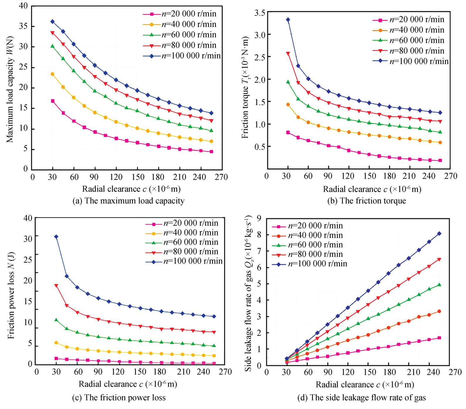
Fig.
11
The lubrication performances versus radial clearance
Fig. 12 shows the variation of 𝑊max, 𝑇𝑟, 𝑁 and 𝑄𝑧 with top foil thickness 𝑡t under different radial clearances. It can be seen that 𝑊max increases with 𝑡t. 𝑇𝑟 and 𝑁 increase with 𝑡t. However, the increasing trend is no longer obvious when 𝑡t is greater than 0.11×10⁻³ m. 𝑄𝑧 presents a significant increase with 𝑡t at large radial clearance.
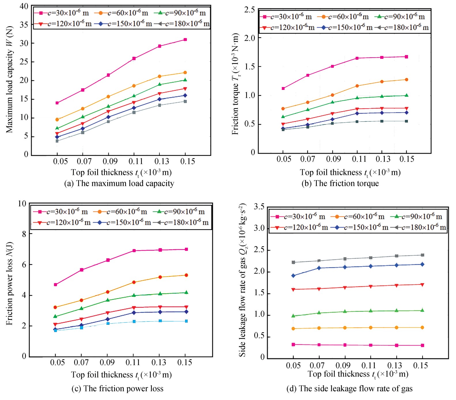
Fig.
12
The lubrication performances versus top foil thickness
Fig. 13 shows the variation of 𝑊max, 𝑇𝑟, 𝑁 and 𝑄𝑧 with bump foil thickness 𝑡b under different radial clearances. It can be known that 𝑊max, 𝑇𝑟, 𝑁 increase with 𝑡b and the increasing trend is more significant with smaller radial clearance. 𝑄𝑧 presents a significant increase with 𝑡b at larger radial clearance.
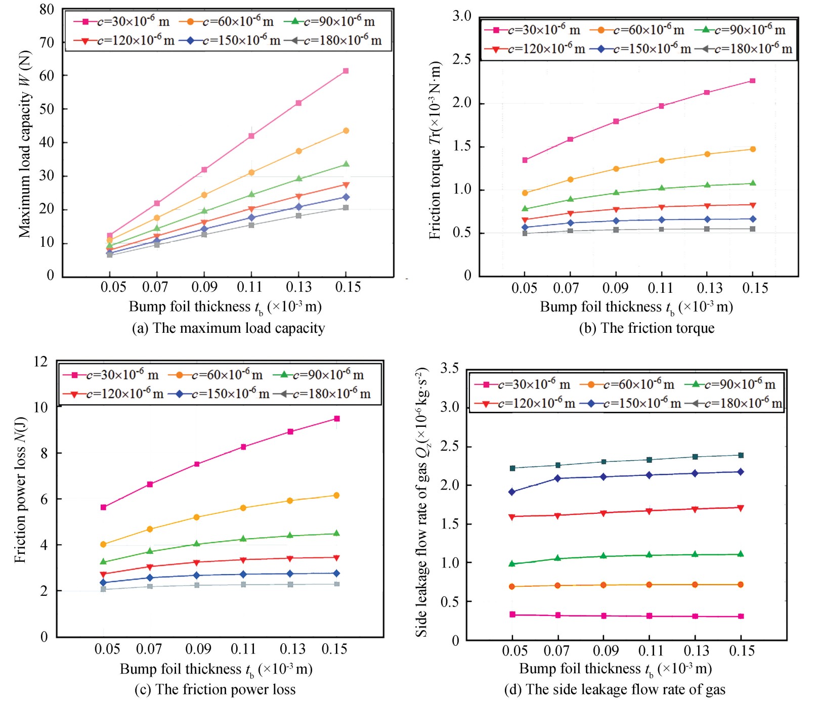
Fig.
13
The lubrication performances versus bump foil thickness
Fig.14 shows the variation of 𝑊max, 𝑇𝑟, 𝑁 and 𝑄𝑧 with bump arch half-length 𝑙 under different radial clearances. It can be known that 𝑊max, 𝑇𝑟, 𝑁 decrease with 𝑙 and the decreasing trend is more significant with smaller radial clearance. 𝑄𝑧 presents a significant decrease trend as 𝑙 increases at larger radial clearance. Fig.15 shows the variation of 𝑊max, 𝑇𝑟, 𝑁 and 𝑄𝑧 with bump arch radius 𝑅0 under different radial clearances. It can be seen that 𝑊max, 𝑇𝑟, 𝑁 and 𝑄𝑧 do not change significantly with 𝑅0.
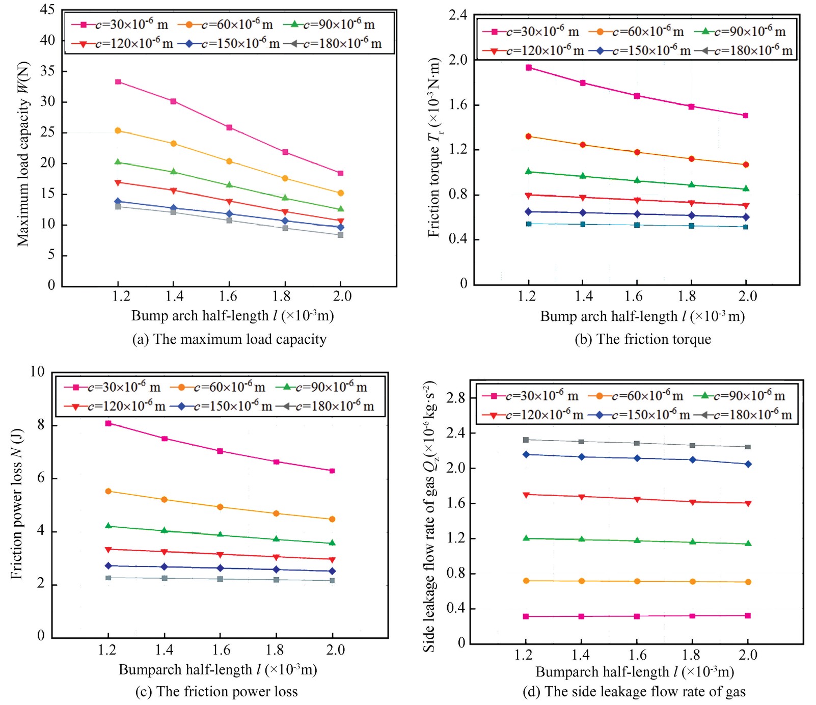
Fig.
14
The lubrication performances versus bump arch half-length
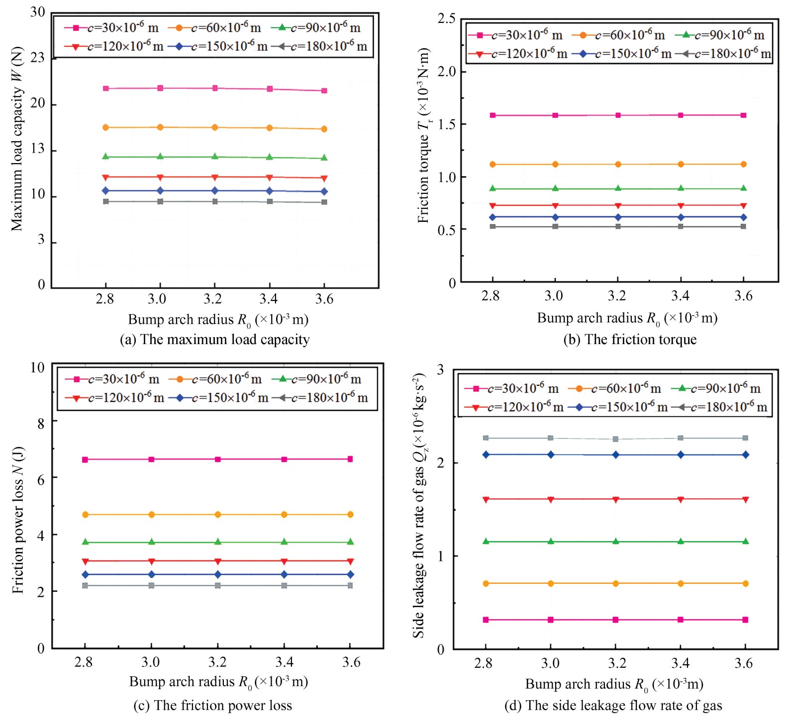
Fig.
15
The lubrication performances versus bump arch radius
2.4 Influences of Radial Clearance on Dynamic Performances
Utilizing the dynamic calculation model of bearings established in this study and the parameters in Table 1, the dynamic performance coefficients with radial clearance 𝑐 under different rotational speeds were calculated when the whirl frequency ratio 𝑣=1 of the rotor and the load 𝑊=5 N.
Fig. 16 shows that 𝐾𝑥𝑥 and 𝐾𝑦𝑦 decrease with radial clearance but increase with rotational speed. The result echoes the situation where 𝑊max varies with the radial clearance, i.e. when the radial clearance becomes large, 𝑊max approaches zero, so the main stiffness coefficients also approach zero.
The cross-stiffness coefficient 𝐾𝑥𝑦 peaks before declining toward zero with radial clearance, while increasing with rotational speed. 𝐾𝑦𝑥 initially increases and then decreases with rotational speed, and initially decreases and then increases toward zero with radial clearance.Fig.17 reveals decreasing 𝐶𝑥𝑥 and 𝐶𝑦𝑦 with larger radial clearance and higher rotational speed. 𝐶𝑥𝑦 increases with radial clearance and gradually approaches zero. 𝐶𝑦𝑥 decreases and then increases towar 𝑑 zero with radial clearance.
2.5 Influences of Foils' Structural Parameters on Dynamic Performances
The dynamic coefficients versus structural parameters of foils at different radial clearances were calculated when 𝑊=5 N.
Fig.18 demonstrates that dynamic stiffness coefficients versus top foil thickness 𝑡ₜ. 𝐾𝑥𝑥 and 𝐾𝑦𝑦 increase as 𝑡ₜ increases, and the increasing trend becomes more significant with smaller radial clearances. 𝐾𝑥𝑦 initially decreases and then increases as 𝑡ₜ increases. 𝐾𝑦𝑥 decreases with 𝑡ₜ.
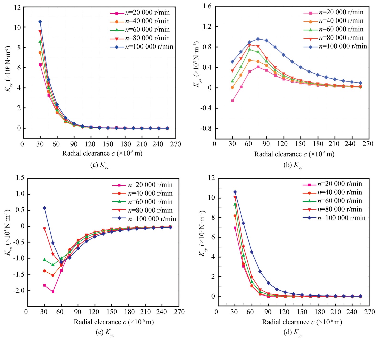
Fig.
16
Stiffness coefficients versus radial clearance
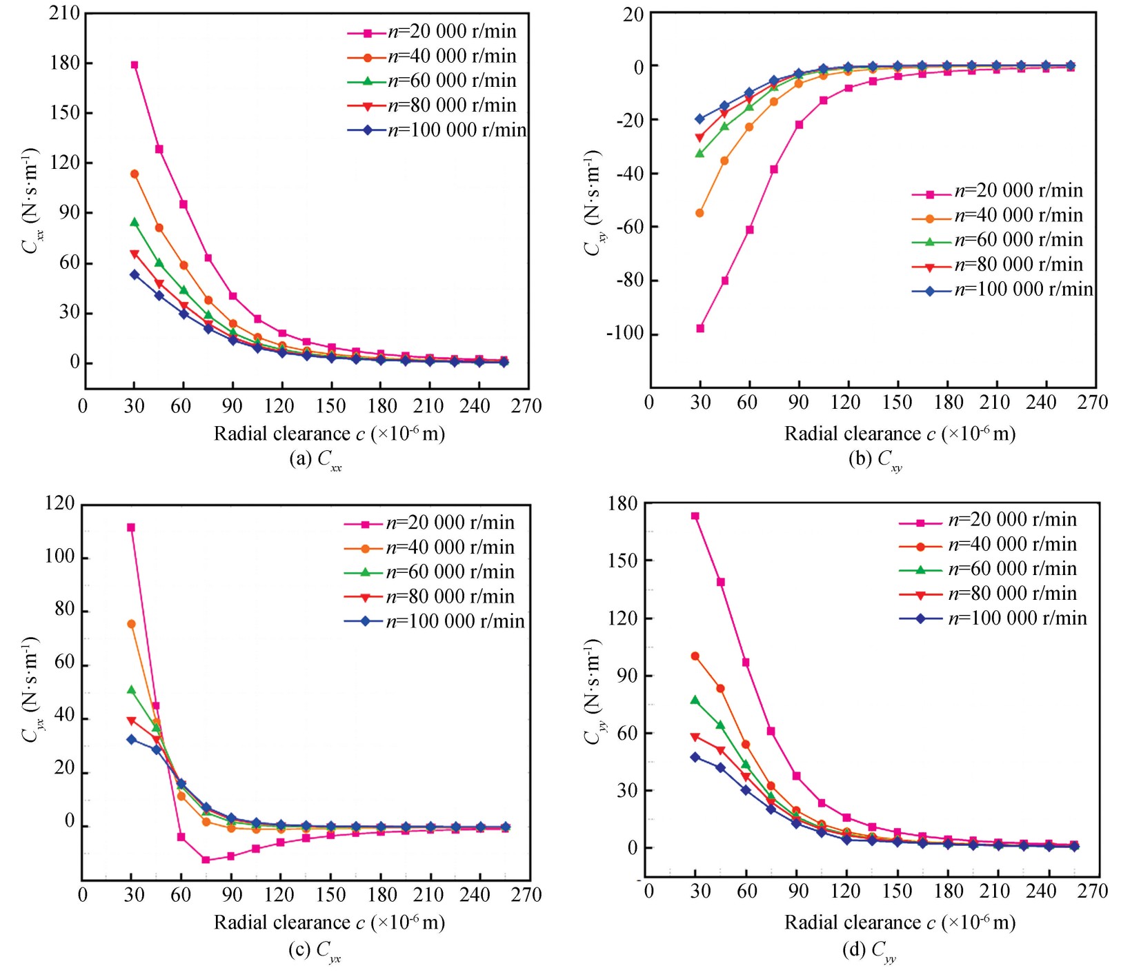
Fig.
17
Damping coefficients versus radial clearance
Fig.19 demonstrates that dynamic damping coefficients versus 𝑡ₜ under different radial clearances. 𝐶𝑥𝑥 and 𝐶𝑦𝑦 increase as 𝑡ₜ increases. However, 𝐶𝑥𝑦 and 𝐶𝑦𝑥 decrease with 𝑡ₜ.
Fig.20 shows that the dynamic stiffness coefficients versus bump foil thickness 𝑡b. 𝐾𝑥𝑥, 𝐾𝑦𝑦 and 𝐾𝑥𝑦 increase as 𝑡b increases, and the influence is more significant with smaller radial clearances. 𝐾𝑦𝑥 decreases with 𝑡b.
Fig.21 demonstrates that dynamic damping coefficients versus 𝑡b under different radial clearances. It can be seen that 𝐶𝑥𝑥, 𝐶𝑦𝑦, 𝐶𝑥𝑦 and 𝐶𝑦𝑥 increase as 𝑡b increases.
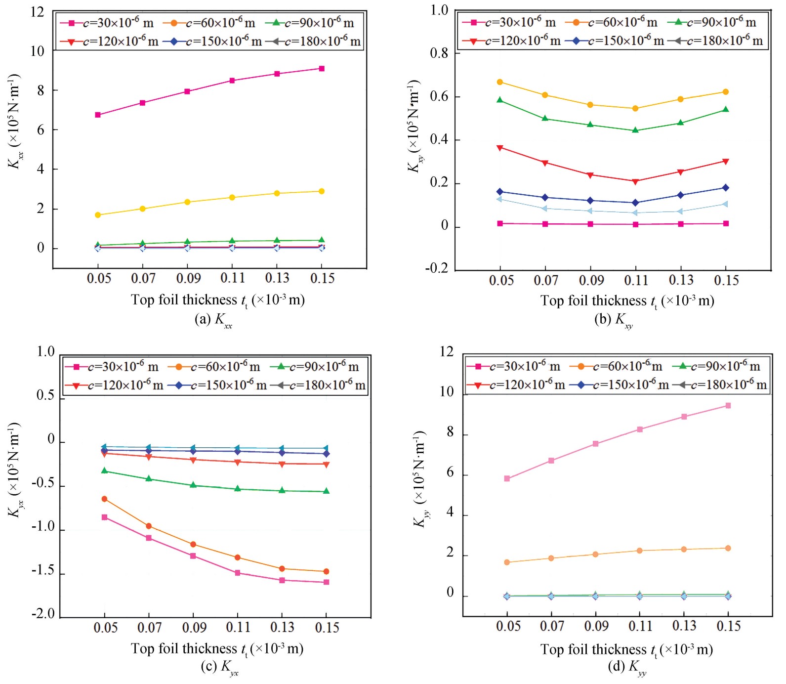
Fig.
18
Stiffness coefficients versus top foil thickness
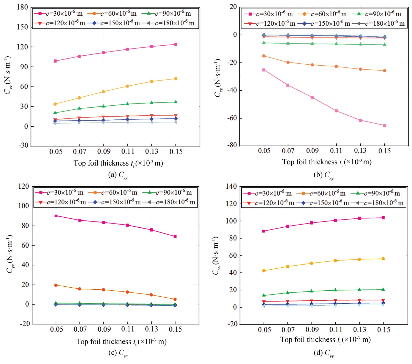
Fig.
19
Damping coefficients versus top foil thickness
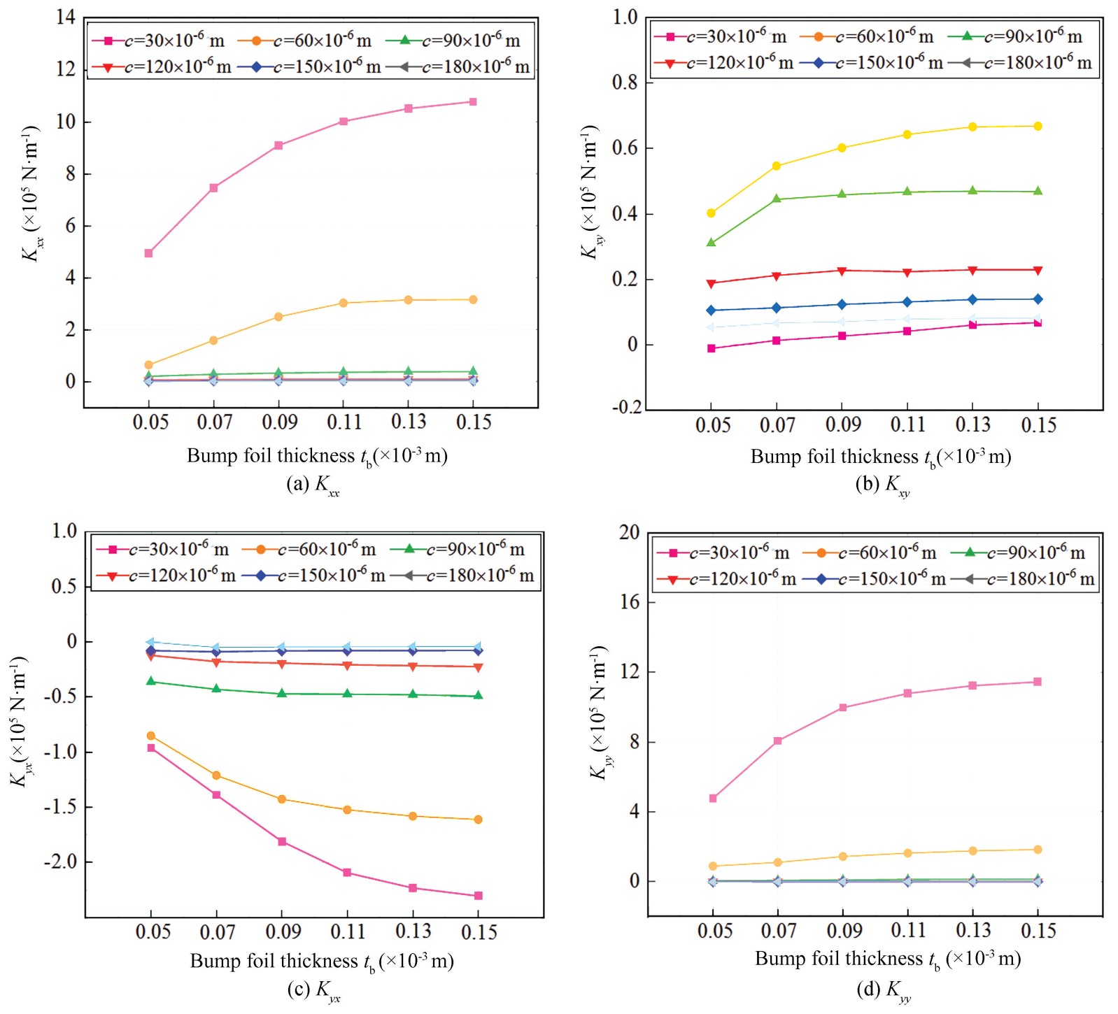
Fig.
20
Stiffness coefficients versus bump foil thickness
Fig.22 demonstrates how dynamic stiffness coefficients change with bump arch half-length 𝑙 across different radial clearances. 𝐾𝑥𝑥 and 𝐾𝑦𝑦 increase as 𝑙 increases, and the increasing trend becomes more significant with smaller radial clearances. 𝐾𝑥𝑦 decreases with 𝑙, but 𝐾𝑦𝑥 varies insignificantly.
Fig. 23 demonstrates that dynamic damping coefficients versus 𝑙 under different radial clearances. It can be seen that 𝐶𝑥𝑥, 𝐶𝑦𝑦, 𝐶𝑥𝑦 and 𝐶𝑦𝑥 decrease as 𝑙 increases.
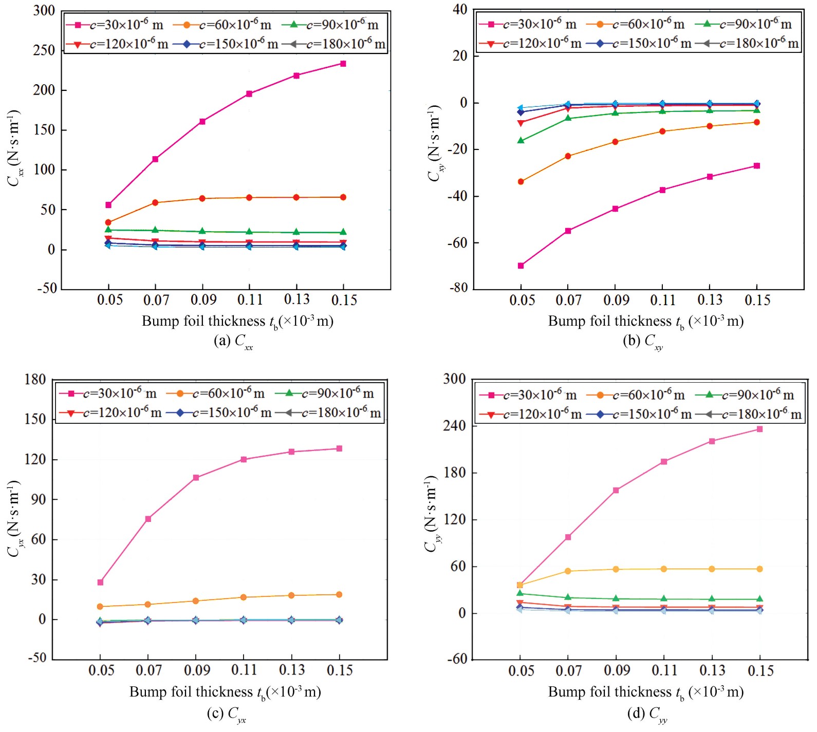
Fig.
21
Damping coefficients versus bump foil thickness
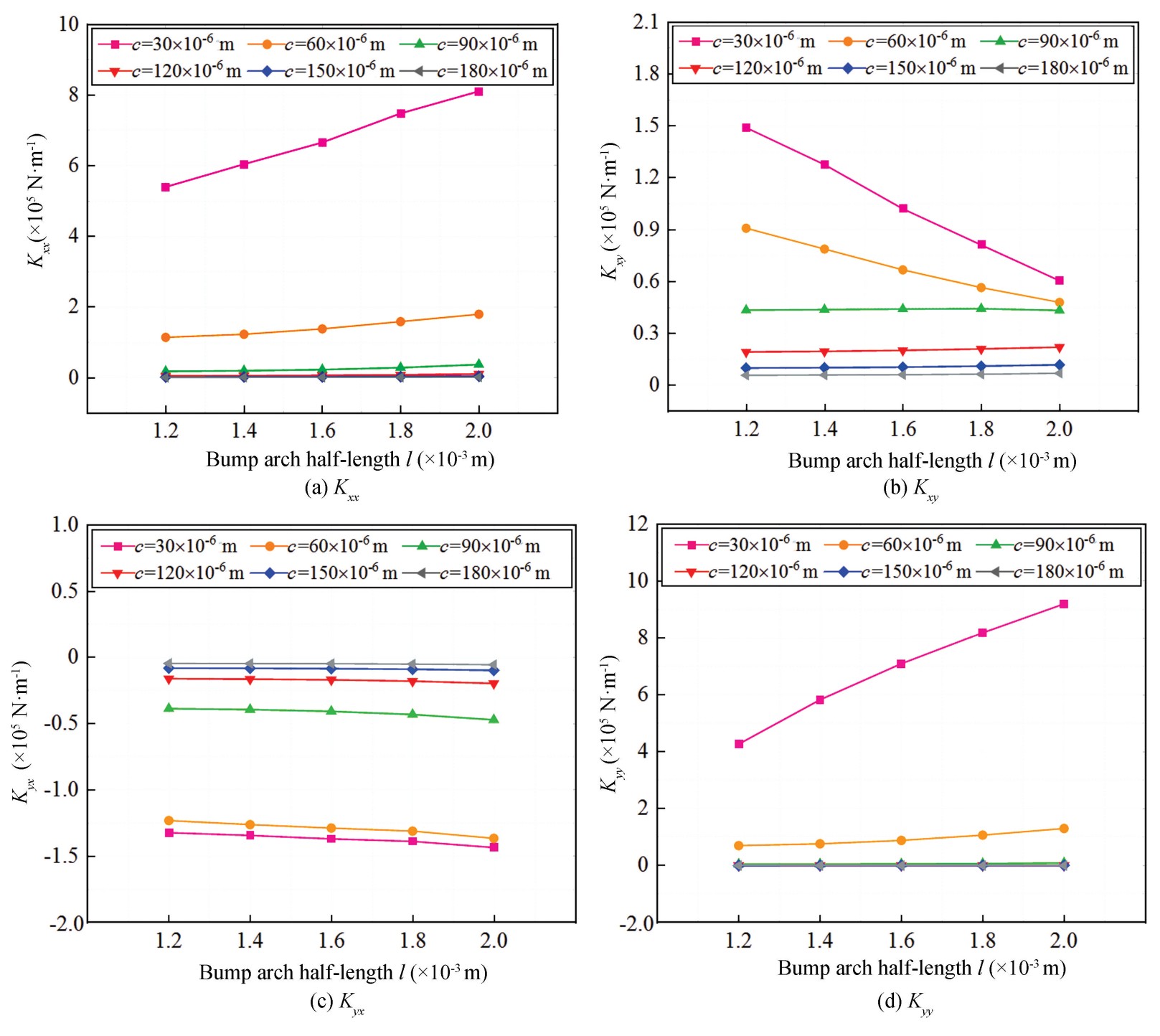
Fig.
22
Stiffness coefficients versus bump arch half-length
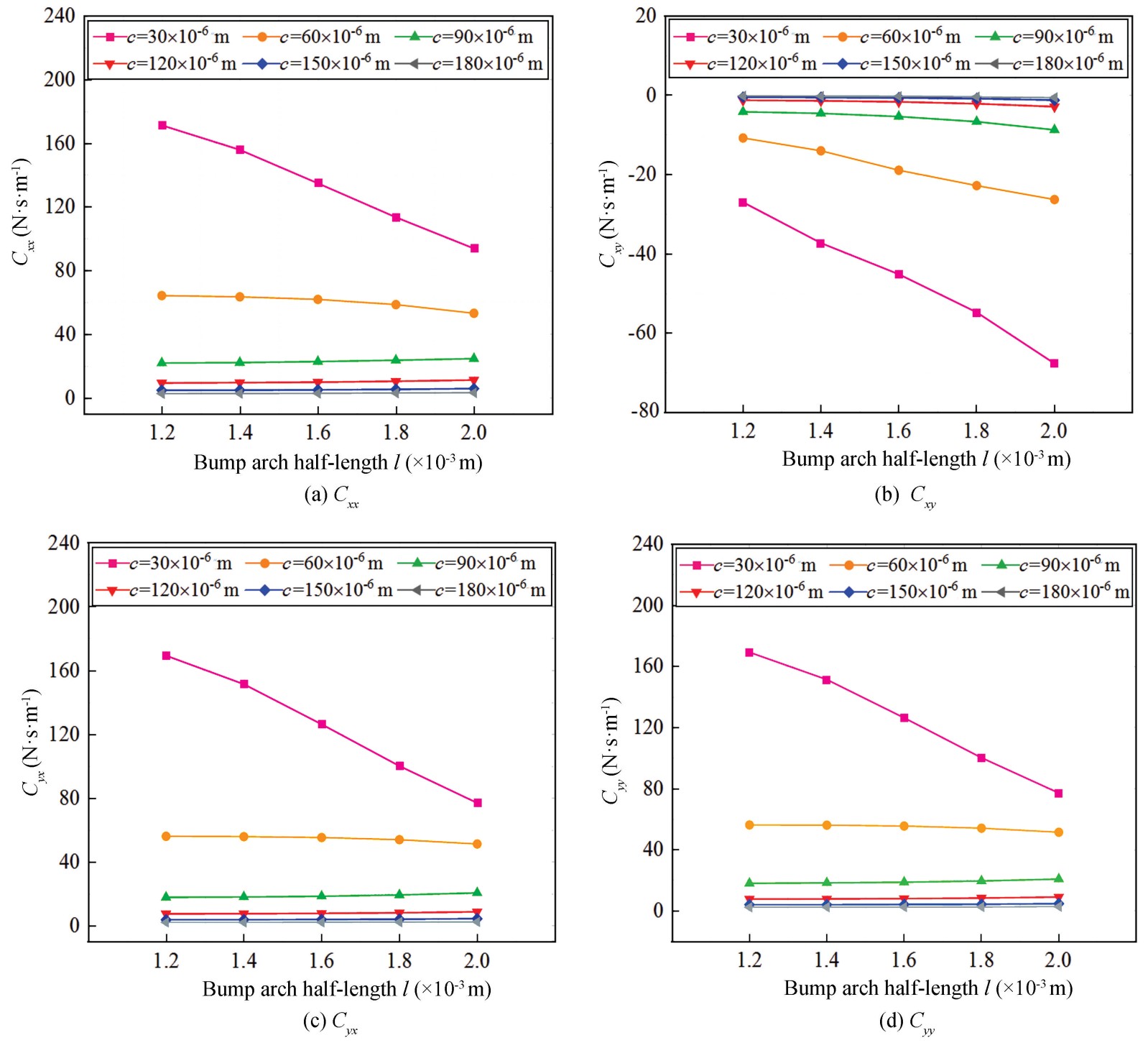
Fig.
23
Damping coefficients versus bump arch half-length
Fig.24 and Fig.25 present dynamic stiffness and damping coefficients versus bump arch radius 𝑅0 under different radial clearances, respectively. All eight coefficients change slightly with 𝑅0.
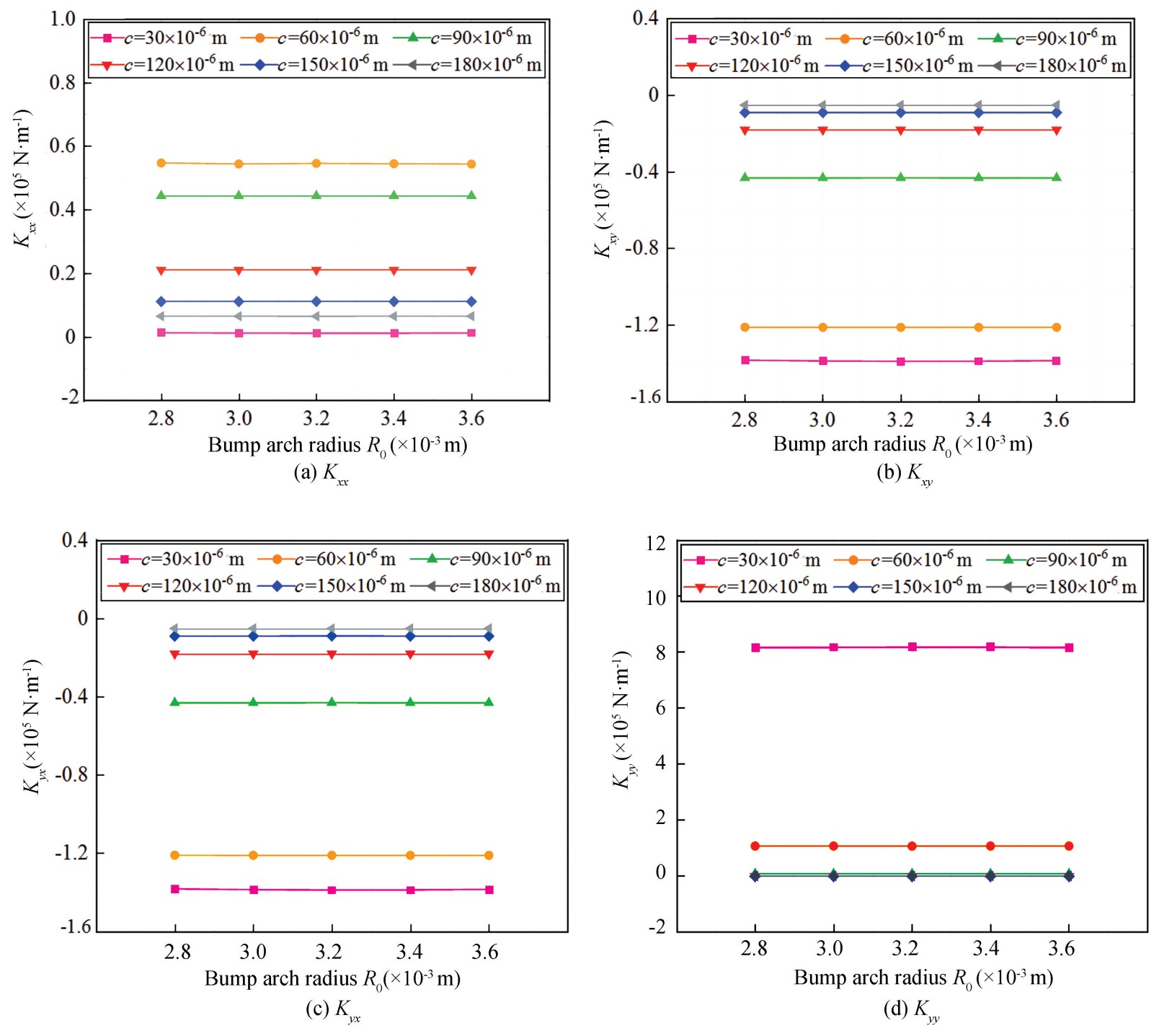
Fig.
24
Stiffness coefficients versus bump arch radius
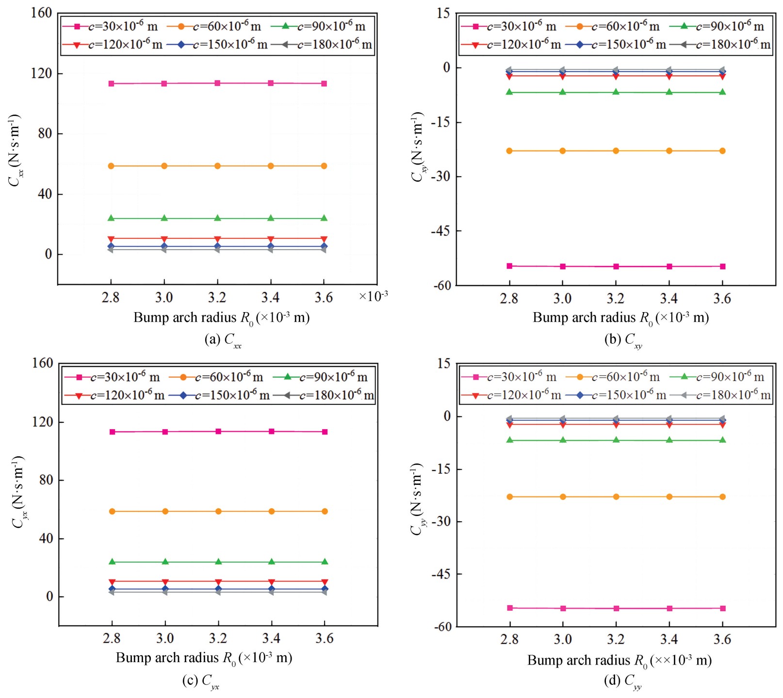
Fig.
25
Damping coefficients versus bump arch radius
3 Conclusions
1) A mechanical model simplifying the foil structure of the bearing as a two-dimensional thin plate finite element model with an elastic support is established by use of the theory of elasticity. The calculation model comprehensively considers the frictions and the interactive forces of bumps. A fluid-solid coupling model for the bearing is established using the compressible gas Reynolds equation. The perturbation method is applied to develop a dynamic model. Using the finite difference method and MATLAB programming, a precise calculation method for lubrication and dynamic performances is established. The friction torque measurements experimentally validated the reliability of the theoretical model.
2) The lubrication performances under varying radial clearances and rotational speeds are investigated. 𝑃max increases and 𝐻min decreases with radial clearance. 𝑃max decreases and 𝐻min increases with rotational speed. The maximum load capacity decreases with radial clearance and increases with rotational speed. Friction torque and friction power loss decrease with radial clearance and increase with rotational speed. The side leakage flow rate of gas increases with radial clearance and rotational speed.
3) The lubrication performances under varying foil structural parameters are investigated. The maximum load capacity, friction torque, and friction power increase with top and bump foil thickness but decrease with bump arch half-length. Besides, the maximum load capacity, friction torque, friction power loss and side leakage flow rate of gas are almost unaffected by bump arch radius.
4) The dynamic performances under varying radial clearances and rotational speeds are investigated. The main stiffness coefficients decrease with radial clearance and increase with rotational speed, which echoes the situation where the maximum load capacity varies with radial clearance. The main damping coefficients decrease with radial clearance and rotational speed.
5) The dynamic performances under varying foil structural parameters are investigated. The main stiffness coefficients increase with top and bump foil thickness and bump arch half-length. The main damping coefficients increase with top and bump foil thickness, but decrease with bump arch half-length. It is noted that the influences become more significant with smaller radial clearances. In addition, the eight dynamic coefficients are almost unaffected by the bump arch radius. The above research results will provide guidance for the design and manufacturing of air foil journal bearings.
Nomenclature